
Base X Machine Addition: Input-Driven Geometric Construction
Loading the math board and drawing, please wait…
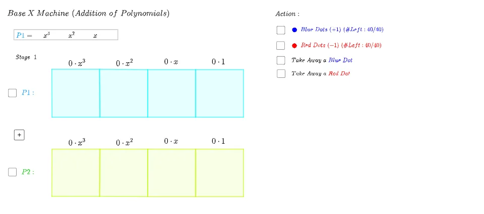
This example demonstrates a “Base X Machine” where an input value is transformed into a corresponding geometric configuration, visually conveying an addition/combination relationship. The key math ideas include input-to-geometry mapping (turning numeric choices into geometric objects), construction-based reasoning such as midline and point/segment relationships, and rule-driven variation using conditional logic and randomized selection. From the construction summary, the build relies on GeoGebra commands and objects such as: Join and Polygon to connect points and form polygonal figures; IndexOf and First to locate specific elements within object lists; If to switch constructions depending on conditions; Shuffle and Random to generate different input arrangements that update the diagram; and Textfield to provide user-controlled input. Text labeling (e.g., text1) is used to display intermediate or final quantities. Suitable for high school through early university use in geometry construction, interactive learning, and modeling-style instruction.
GeoGebra Commands & Parameters
Join({x31N, x32N}) → rx3NJoin({x31P, x32P}) → rx3PJoin({x11N, x12N}) → rx1NJoin({x11P, x12P}) → rx1PJoin({x21N, x22N}) → rx2NJoin({x21P, x22P}) → rx2PPolygon(I_3, J_3, K_3, L_3) → X31, a14, a16, a32, a29Polygon(L_3, M_3, N_3, K_3) → X21, a1, a27, a28, a3Polygon(M_3, P_3, O_3, N_3) → X11, a5, a25, a26, a7Polygon(P_3, Q_3, R_3, O_3) → X01, a9, a17, a24, a10Polygon(S_3, V_3, U_3, T_3) → X32, a23, a20, a21, a22Polygon(V_3, W_3, Z_3, U_3) → X22, a11, a19, a18, a12Polygon(W_3, B_4, A_4, Z_3) → X12, a13, a4, a2, a15Polygon(B_4, C_4, D_4, A_4) → X02, a31, a6, a8, a30Polygon(I_3, L_3, U_3, T_3) → Rx3, r11, r10, r9, r7Polygon(L_3, M_3, Z_3, U_3) → Rx2, r5, r4, r2, r3Polygon(M_3, P_3, A_4, Z_3) → Rx1, r6, r1, r14, r12Polygon(P_3, Q_3, D_4, A_4) → Rx0, r16, r15, r13, r8IndexOf(false, FP) → tmpIIndexOf(false, FN1) → NDtmpIFirst(x31P) → TAtmpIIf(NDtmpI ≟ NDtmpI, true, false) → NDHIf(Length[x31P] - Length[x31N] ≟ Element[Coef1, IndexOf["x^3", Order1]], true, false) → Bx31If(Length[x21P] - Length[x21N] ≟ Element[Coef1, IndexOf["x^2", Order1]], true, false) → Bx21If(Length[x11P] - Length[x11N] ≟ Element[Coef1, IndexOf["x", Order1]], true, false) → Bx11If(Length[x01P] - Length[x01N] ≟ Element[Coef1, IndexOf["", Order1]], true, false) → Bx01Shuffle({1, 2, 3, 4}) → OrderS, {3, 2, 1, 4}Random(-5, 5) → L23Co01Random(-5, 5) → L23Co02Random(-5, 5) → L23Co32Random(-5, 5) → L23Co31Random(-5, 5) → L23Co22Random(-5, 5) → L23Co21Random(-5, 5) → L23Co12Random(-5, 5) → L23Co11If(Length[x32P] - Length[x32N] ≟ Element[Coef2, IndexOf["x^3", Order2]], true, false) → Bx32If(Length[x22P] - Length[x22N] ≟ Element[Coef2, IndexOf["x^2", Order2]], true, false) → Bx22If(Length[x12P] - Length[x12N] ≟ Element[Coef2, IndexOf["x", Order2]], true, false) → Bx12If(Length[x02P] - Length[x02N] ≟ Element[Coef2, IndexOf["", Order2]], true, false) → Bx02Join({x01N, x02N}) → rx0NJoin({x01P, x02P}) → rx0PIf(TAPP ≟ true ∧ TANN ≟ true, true, false) → TAPNFirst(rx0P) → tmpPFirst(rx0N) → tmpNIf(Element[tmpP, 1] ≟ Element[tmpP, 1], true, false) → tPIf(Element[tmpN, 1] ≟ Element[tmpN, 1], true, false) → tNTextfield(Br3) → Ir3Textfield(Br2) → Ir2Textfield(Br1) → Ir1Textfield(Br0) → Ir0Random(0, 5) → L1Co01Random(0, 5) → L1Co02Random(0, 5) → L1Co11Random(0, 5) → L1Co12Random(0, 5) → L1Co21Random(0, 5) → L1Co22Random(0, 5) → L1Co31Random(0, 5) → L1Co32Random(1, 2) → SignL1IndexOf(false, FP) → PDtmpIIf(PDtmpI ≟ PDtmpI, true, false) → PDHIf(x12P ≠ {}, true, false) → TAPHIf(x12N ≠ {}, true, false) → TANH
AI Drawing Prompt Reference
Draw a composite figure made of multiple quadrilaterals arranged in two horizontal rows, with four adjacent quadrilaterals in each row. The upper and lower rows share edges, creating a belt-like visual effect. Each quadrilateral contains internal diagonal or connecting lines, and some are shaded or colored differently. On both sides, there are input or control points connected to the inner quadrilaterals via line segments. The construction starts from the left, generating quadrilaterals sequentially to the right, with random values determining some edge lengths or positions, giving the figure a dynamic, variable appearance.
The prompt above was compiled from the original drawing commands and is for reference only.