
Angle Pairs Builder (More): Constructing and Comparing Angle Correspondences
Loading the math board and drawing, please wait…
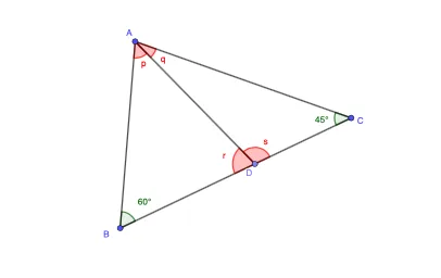
This GeoGebra example demonstrates how to construct and visually compare different “angle pairs” configurations, emphasizing how angle correspondences arise from the same underlying geometric setup. It focuses on geometric construction concepts: creating segments and polygons from key points, defining angles by selecting their rays/segments, and using those angle objects to examine whether multiple paired angles satisfy the intended relationship. The core ideas include angle measurement/representation and the recognition of structured angle correspondences produced by a controlled arrangement of points and lines. Construction highlights, derived from the provided build summary: it uses the GeoGebra commands Segment, Point, Polygon, and Angle; the object list includes multiple labeled points (e.g., A, B, C, D) together with angle-related parameters/objects (e.g., t1, t2, β, f, g, h, i and other angle- or parameter-like entities). Learners can observe how changing the configuration affects the resulting angle pairs. Suitable for middle and high school geometry instruction, classroom demonstration, and students practicing geometric modeling and angle-relation reasoning.
GeoGebra Commands & Parameters
Segment(A, B) → fSegment(B, C) → gSegment(C, A) → hPoint(g) → DSegment(A, D) → iPolygon(A, B, D) → t1, d, a, bPolygon(A, D, C) → t2, c, a_1, d_1Angle(t1) → p, β, rAngle(t2) → q, s, ζ
AI Drawing Prompt Reference
Draw a planar geometric setup starting with three points that form a triangular framework: construct the three segments along the triangle sides between the first, second, and third points. From the side directions of the last two edges, choose a point on the corresponding line as a fourth point, then connect the first point to this fourth point. Build one triangle using the first, second, and fourth points, and define the first angle pair as the angle at the first vertex formed by the rays toward the second and fourth points. Build a second triangle using the first, fourth, and third points, and define the second angle pair as the angle at the first vertex formed by the rays toward the fourth and third points. Display both angle pairs together for visual comparison of how the correspondence changes with the configuration.
The prompt above was compiled from the original drawing commands and is for reference only.