
Angle Construction with Orthogonal Helpers in Geometry
Loading the math board and drawing, please wait…
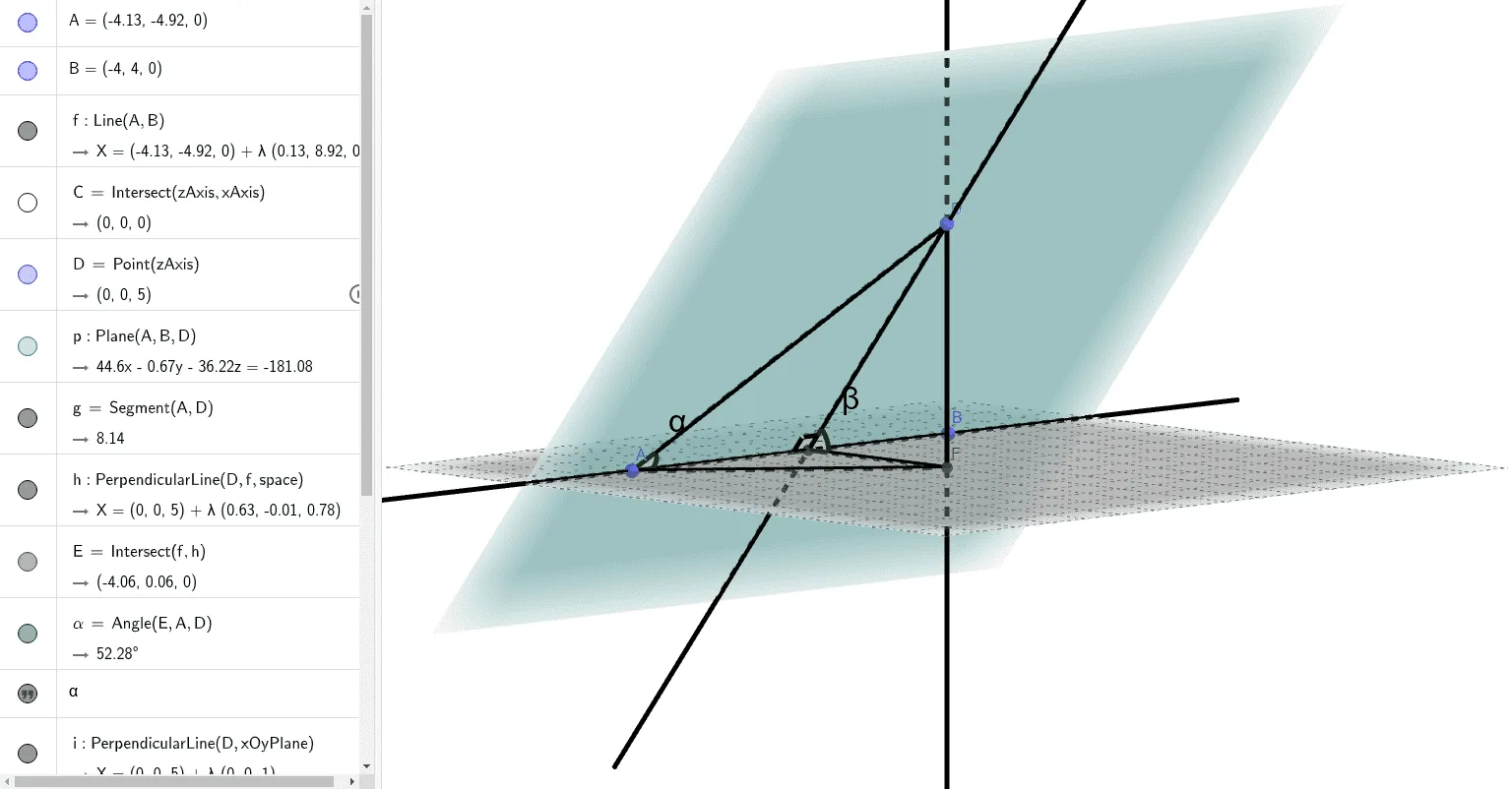
This example demonstrates how to construct and visualize an angle (e.g., an oblique/plane-related angle) using a reference plane and line relationships. It emphasizes building a reliable angle measurement setup with right-angle (orthogonal) auxiliary geometry. Key concepts include Angle measurement, intersections and defining construction points, plane geometry via Plane, and the use of OrthogonalLine to create perpendicular helper lines that make the angle construction clear and verifiable. Construction workflow in GeoGebra: Line to draw the required lines, Intersect to obtain critical intersection points, Point to manage key vertices/points, Plane to establish the reference plane, Segment to form visible boundary edges, OrthogonalLine to generate the perpendicular helper, and finally Angle to compute and label the target angles (α, β, γ) with accompanying text objects for readable results. Suitable for middle school to high school geometry instruction and classroom demonstrations on angle construction and geometric problem-solving.
GeoGebra Commands & Parameters
Line(A, B) → fIntersect(zAxis, xAxis) → CPoint(zAxis) → DPlane(A, B, D) → pSegment(A, D) → gOrthogonalLine(D, f, space) → hIntersect(f, h) → EAngle(E, A, D) → αOrthogonalLine(D, xOyPlane) → iIntersect(i, xOyPlane) → FSegment(E, F) → jAngle(F, E, D) → βSegment(A, F) → kAngle(D, E, A) → γ
AI Drawing Prompt Reference
Draw an angle construction diagram with line segment AB intersecting the z-axis at point C, point D on the z-axis, a reference plane p defined by points A, B, and D, line segment AD, a perpendicular helper line h from point D intersecting line f at point E, angle α calculated at point E, another perpendicular helper line i from point D intersecting the xOy plane at point F, line segment EF, angle β calculated at point F, and line segment AF, with angle γ calculated at point D.
The prompt above was compiled from the original drawing commands and is for reference only.