
Anamorphic Images: Geometric Construction and Principles
Loading the math board and drawing, please wait…
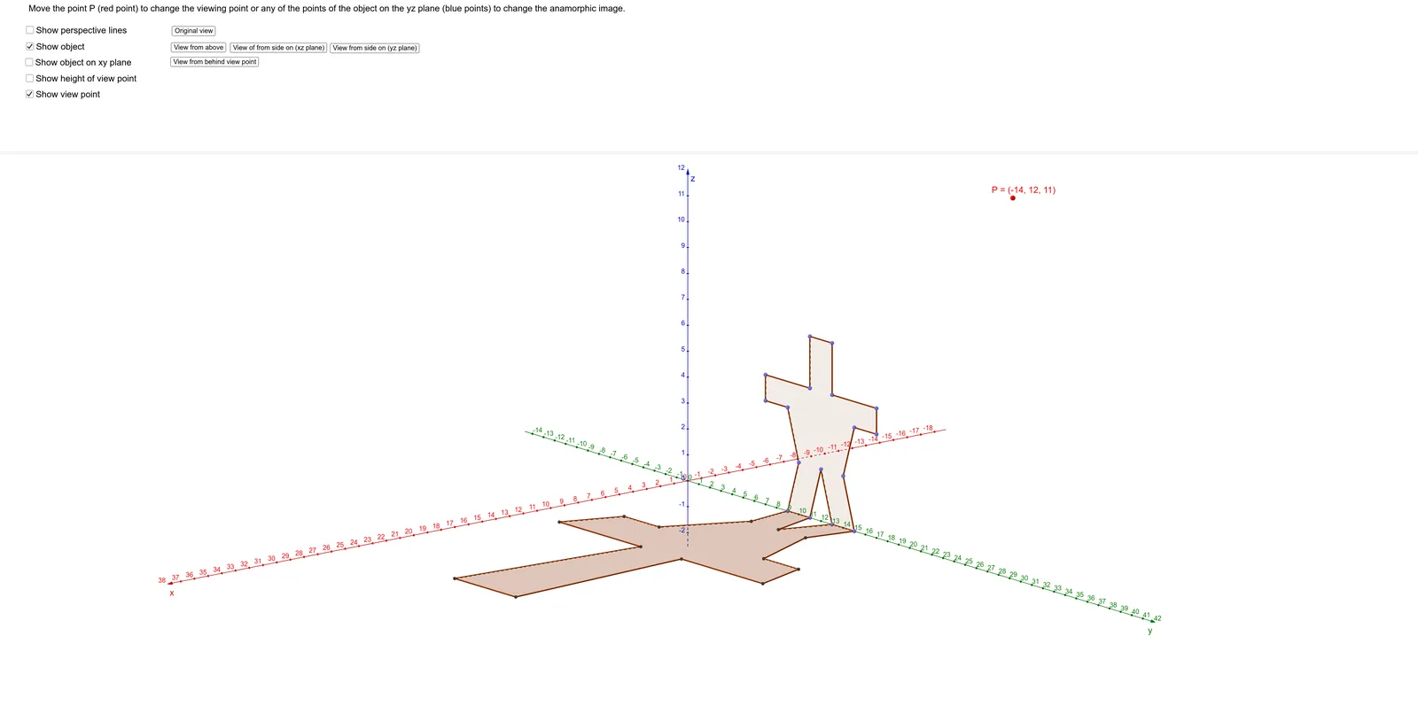
This GeoGebra example demonstrates how to construct anamorphic images, a visual art form where distorted projections appear normal from a specific viewpoint. The core mathematical concepts involve similar triangles, right triangles, the tangent function, coordinate geometry, and elements of solid geometry and linear optimization. The construction uses commands such as Point, PointIn, Polygon, Segment, OrthogonalLine, and Intersect, with objects including points A through O, Q, R, polygon poly1, and various segments and lines. It is suitable for high school and college students or math enthusiasts to explore projective geometry, similarity, and the application of functions in art.
GeoGebra Commands & Parameters
Point(yAxis) → APoint(yAxis) → BPointIn(eq1) → CPoint(yAxis) → DPointIn(eq1) → EPointIn(eq1) → FPointIn(eq1) → GPointIn(eq1) → HPointIn(eq1) → IPointIn(eq1) → JPointIn(eq1) → KPointIn(eq1) → LPointIn(eq1) → MPointIn(eq1) → NPointIn(eq1) → OPointIn(eq1) → QPointIn(eq1) → RPolygon(B, C, L, M, N, O, R, Q, A, D, E, F, G, H, I, J, K) → poly1, b, k, l, m, n, o, r, q, a, c, d, e, f, g, h, i, jPolygon(A, J_1, B_1, A_1, Z, E, D, U, B, K_1, I_1, H_1, G_1, F_1, E_1, D_1, C_1) → poly2, a_1, c_1, b_1, p, z_1, e_2, d_2, u, b_2, j_1, k_1, i_1, h_1, g_1, f_1, e_1, d_1Segment(P, F_1) → sSegment(P, E_1) → tSegment(P, D_1) → l_1Segment(P, C_1) → m_1Segment(P, B_1) → n_1Segment(P, A_1) → p_1Segment(P, Z) → q_1Segment(P, E) → r_1Segment(P, D) → s_1Segment(P, U) → t_1Segment(P, G_1) → f_2Segment(P, H_1) → g_2Segment(P, I_1) → h_2Segment(P, K_1) → i_2Segment(P, J_1) → j_2Segment(B, P) → k_2Segment(P, A) → l_2Polygon(A, C_2, S_1, R_1, Q_1, E, D, N_1, B, D_2, B_2, A_2, Z_1, W_1, V_1, U_1, T_1) → poly3, m_2, f_3, g_3, h_3, i_3, j_3, k_3, l_3, m_3, n_2, p_2, q_2, r_2, s_2, t_2, a_2, c_2OrthogonalLine(P, p_3) → n_3Intersect(n_3, p_3) → E_2Segment(P, E_2) → q_3
AI Drawing Prompt Reference
Create an anamorphic image that appears normal from a specific viewpoint. Start by creating points A and B on the y-axis, then create points C to O using a given equation. Construct a polygon poly1 with these points. Next, create another polygon poly2 that partially overlaps with poly1. From point P, draw segments to each vertex of poly2, then construct lines perpendicular to these segments and find their intersection point E2. Finally, connect P and E2.
The prompt above was compiled from the original drawing commands and is for reference only.