
4-Stroke Engine Simulation
Loading the math board and drawing, please wait…
In collections
Sine and Cosine Functions
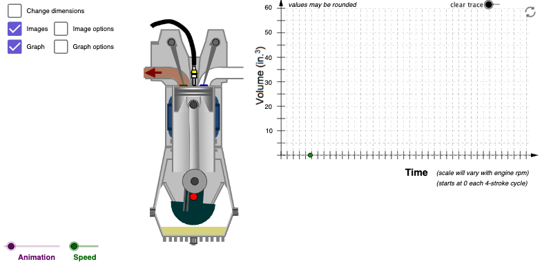
This example demonstrates a graphical simulation of a 4-stroke engine, showing the relationship between piston displacement and time. Key math concepts include function graphs, trigonometry, geometric constructions, and parametric equations. It utilizes commands like Line, Circle, Intersect, Point, If, Angle, OrthogonalLine, Segment, Mirror, Polygon, Midpoint, Vector, Conic, CircleSector, and Sequence in GeoGebra. Suitable for high school students and engineers studying engine mechanics and mathematical modeling.
GeoGebra Commands & Parameters
Line(Crankshaft, Crankshaft + (0, 10)) → VerticalCircle(Crankpin, (scaleFactor * rodLength)) → ConnectingRodCircleIntersect(ConnectingRodCircle, Vertical, 2) → WristpinLine(Crankpin, Crankshaft) → iPoint(i) → CounterBalCenterPtIf(angleNumAdj > 0 ∧ angleNumAdj < 0.1, ((-1 * 1.5) * angleNumAdj), If[angleNumAdj ≥ 0.1 ∧ angleNumAdj < 0.2, ((-1 * 1.5) * ((-angleNumAdj) + 0.2)), 0]) → valve1MotionVertAngle(CrankShaftRadius, Crankshaft, Rotate[CrankShaftRadius, α, Crankshaft]) → angleLine(Wristpin, Crankpin) → bOrthogonalLine(Crankpin, b) → cOrthogonalLine(Wristpin, b) → dCircle(Crankpin, 0.2) → rodbasecircledarkCircle(Wristpin, 0.2) → fSegment(TopDeadCenter + ((-1 * 0.4), 0), TopDeadCenter + (0.4, 0)) → TDCSegSegment(BottomDeadCenter + ((-1 * 0.4), 0), BottomDeadCenter + (0.4, 0)) → BDCSegCircle(Crankpin, 0.4) → kOrthogonalLine(Crankpin, i) → jOrthogonalLine(Crankshaft, i) → lCircle(CounterBalCenterPt, 0.9) → qIntersect(k, j) → C, DIntersect(q, i, 2) → AOrthogonalLine(A, i) → mCircle(A, 0.4) → pIntersect(p, m, 1) → BIntersect(rodbasecircledark, c, 1) → rodImageBLIntersect(rodbasecircledark, c, 2) → rodImageBRIntersect(f, d, 1) → rodImageTRIntersect(f, d, 2) → rodImageTLCircle(CounterBalCenterPt, 0.2) → rIntersect(r, i, 1) → HOrthogonalLine(CounterBalCenterPt, i) → sIntersect(q, s, 1) → IIntersect(q, s, 2) → JCircle(H, 0.5) → tIntersect(t, i, 2) → KCircle(K, 0.4) → c_1OrthogonalLine(K, i) → a_1Intersect(c_1, a_1, 1) → LIntersect(c_1, a_1, 2) → MSegment(Crankshaft, Crankpin) → crankPinOffsetSkeletonSegment(Wristpin, Crankpin) → rodSkeletonSegment(PistonHeadTop + (0, (-1 * 0.05)), Wristpin) → CompressionHeightSegLine(Valve1CamPt, Valve1HalfHeight) → aOrthogonalLine(Valve1HalfHeight, a) → eCircle(Valve1HalfHeight, 0.28) → gIntersect(g, e, 2) → Valve1CamTLIntersect(g, e, 1) → Valve1CamTRMirror(Valve1HalfHeight, Valve1CamPt) → Valve1HalfHeight'Circle(Valve1HalfHeight', 0.28) → d_1OrthogonalLine(Valve1HalfHeight', a) → b_1Intersect(d_1, b_1, 2) → Valve1CamBRIntersect(d_1, b_1, 1) → Valve1CamBLPolygon(Crankshaft + (0.22, 0.01 + (scaleFactor * deckHeight) + valve1MotionVert), Crankshaft + (0.61, 0.01 + (scaleFactor * deckHeight) + valve1MotionVert), Crankshaft + (0.56, 0.08 + (scaleFactor * deckHeight) + valve1MotionVert), Crankshaft + (0.27, 0.08 + (scaleFactor * deckHeight) + valve1MotionVert)) → valve1, e_1, f_1, g_1, h_1Circle(Crankpin, 0.5) → hCircle(Crankpin, 0.5) → rodbasecirclelargelightMidpoint(TopDeadCenter, BottomDeadCenter) → StrokeCenterPolygon(displBL, displBR, displTR, displTL) → polyStroke1, e_2, f_2, g_2, n_1If(angleNum < 150, 153, If[angleNum < 165, 102, If[angleNum < 180, 51, 0]]) → polyStroke2RdNumPolygon(displBL, displBR, displTR, displTL) → polyStroke2, displbl, displbr, displtr, displtlIf(angleNum < 180, 255, If[angleNum < 195, 204, If[angleNum < 210, 153, 102]]) → polyStroke2BlueNumPolygon(displBL, displBR, displTR, displTL) → polyStroke3, displbl_1, displbr_1, displtr_1, displtl_1Polygon(displBL, displBR, displTR, displTL) → polyStroke4, displbl_2, displbr_2, displtr_2, displtl_2Point(i) → EMirror(D, i) → D'''If(angleNum < 75, 360 + angleNum, angleNum) → valve4NumAdjIf(valve4NumAdj > 315 ∧ valve4NumAdj < 360, ((-1 * 0.0034) * (valve4NumAdj - 315)), If[valve4NumAdj ≥ 360 ∧ valve4NumAdj < 405, (0.0034 * (valve4NumAdj - 315 - 405)) + 1.07, 0]) → valve4MotionVertPolygon(Crankshaft + ((-1 * 0.22), 0.01 + (scaleFactor * deckHeight) + valve4MotionVert), Crankshaft + ((-1 * 0.61), 0.01 + (scaleFactor * deckHeight) + valve4MotionVert), Crankshaft + ((-1 * 0.56), 0.08 + (scaleFactor * deckHeight) + valve4MotionVert), Crankshaft + ((-1 * 0.27), 0.08 + (scaleFactor * deckHeight) + valve4MotionVert)) → valve4, i_1, j_1, k_1, l_1Mirror(Valve4HalfHeight, Valve4CamPt) → Valve4HalfHeight'Circle(Valve4HalfHeight', 0.28) → p_1Circle(Valve4HalfHeight, 0.28) → q_1Line(Valve4HalfHeight', Valve4HalfHeight) → m_1OrthogonalLine(Valve4HalfHeight', m_1) → r_1OrthogonalLine(Valve4HalfHeight, m_1) → s_1Intersect(p_1, r_1, 2) → Valve4CamBRIntersect(p_1, r_1, 1) → Valve4CamTRIntersect(q_1, s_1, 1) → Valve4CamTLIntersect(q_1, s_1, 2) → Valve4CamBLPolygon(Crankshaft + (0.38, 0.08 + (scaleFactor * deckHeight) + valve1MotionVert), Crankshaft + (0.44, 0.08 + (scaleFactor * deckHeight) + valve1MotionVert), Crankshaft + (0.94, 1.62 + (scaleFactor * deckHeight) + valve1MotionVert), Crankshaft + (0.74, 1.68 + (scaleFactor * deckHeight) + valve1MotionVert)) → valve1Rod, t_1, a_2, b_2, c_2Polygon(Crankshaft + ((-1 * 0.38), 0.08 + (scaleFactor * deckHeight) + valve4MotionVert), Crankshaft + ((-1 * 0.44), 0.08 + (scaleFactor * deckHeight) + valve4MotionVert), Crankshaft + ((-1 * 0.94), 1.62 + (scaleFactor * deckHeight) + valve4MotionVert), Crankshaft + ((-1 * 0.74), 1.68 + (scaleFactor * deckHeight) + valve4MotionVert)) → valve4Rod, d_2, h_2, i_2, j_2Vector(StrokeCenter, StrokeCenter + (0, ((-1 * scaleFactor) * crankPin))) → strokeVectorBotomVector(StrokeCenter, StrokeCenter + (0, (scaleFactor * crankPin))) → strokeVectorTopVector(StrokeCenter, StrokeCenter + (((0.5 * scaleFactor) * bore), 0)) → boreVectorRtVector(StrokeCenter, StrokeCenter + ((((-1 * 0.5) * scaleFactor) * bore), 0)) → boreVectorLVector(CylModBDC, CylModBDC + ((((-1 * 0.5) * scaleFactor) * bore), 0)) → cylModBoreVectorLVector(CylModBDC, CylModBDC + (((0.5 * scaleFactor) * bore), 0)) → cylModBoreVectorRtConic(F, G, N, O, P) → k_2Segment(Wristpin + ((((-1 * 0.5) * scaleFactor) * bore), (scaleFactor * compressionHeight)), Wristpin + (((0.5 * scaleFactor) * bore), (scaleFactor * compressionHeight))) → pistonTopSkeleSegLine(Valve4CamBR, Valve4CamBL) → nLine(Valve4CamTR, Valve4CamTL) → l_2OrthogonalLine(Valve4CamPt, n) → m_2Mirror(Valve4CamBL2, m_2) → Valve4CamBL2'OrthogonalLine(Valve4CamPt, m_2) → n_2Mirror(Valve4CamBL2, n_2) → Valve4CamBL2'_1Mirror(Valve4CamBL2'_1, m_2) → Valve4CamBL2'_2Segment(CylinderTopCenter, CylinderTopCenter + (-1, 0.5)) → ImpactSeg2Segment(CylinderTopCenter, CylinderTopCenter + ((-1 * 1.75), (-1 * 0.45))) → ImpactSeg3Segment(CylinderTopCenter, CylinderTopCenter + ((-1 * 0.75), (-1 * 0.75))) → ImpactSeg4Segment(CylinderTopCenter, CylinderTopCenter + ((-1 * 0.25), (-1 * 1.5))) → ImpactSeg5Segment(CylinderTopCenter, CylinderTopCenter + (0.4, (-1 * 1.25))) → ImpactSeg1Segment(CylinderTopCenter, CylinderTopCenter + (1, -1)) → ImpactSeg6Segment(CylinderTopCenter, CylinderTopCenter + (2, (-1 * 0.75))) → ImpactSeg7Segment(CylinderTopCenter, CylinderTopCenter + (1.75, (-1 * 0.25))) → ImpactSeg8Mirror(CylinderTopCenter, CylinderTopCenter) → CylinderTopCenter'Mirror(CylinderTopCenter + ((-1 * 1.75), (-1 * 0.45)), CylinderTopCenter) → QSegment(CylinderTopCenter', Q) → ImpactSeg3'Mirror(CylinderTopCenter, CylinderTopCenter') → CylinderTopCenter'_1Mirror(CylinderTopCenter + ((-1 * 0.75), (-1 * 0.75)), CylinderTopCenter') → RSegment(CylinderTopCenter'_1, R) → ImpactSeg4'Mirror(CylinderTopCenter, CylinderTopCenter'_1) → CylinderTopCenter'_2Mirror(CylinderTopCenter + ((-1 * 0.25), (-1 * 1.5)), CylinderTopCenter'_1) → SSegment(CylinderTopCenter'_2, S) → ImpactSeg5'Mirror(CylinderTopCenter, CylinderTopCenter'_2) → CylinderTopCenter'_3Mirror(CylinderTopCenter + (0.4, (-1 * 1.25)), CylinderTopCenter'_2) → TSegment(CylinderTopCenter'_3, T) → ImpactSeg1'Mirror(CylinderTopCenter, CylinderTopCenter'_3) → CylinderTopCenter'_4Mirror(CylinderTopCenter + (1, -1), CylinderTopCenter'_3) → USegment(CylinderTopCenter'_4, U) → ImpactSeg6'Mirror(CylinderTopCenter, CylinderTopCenter'_4) → CylinderTopCenter'_5Mirror(CylinderTopCenter + (2, (-1 * 0.75)), CylinderTopCenter'_4) → VSegment(CylinderTopCenter'_5, V) → ImpactSeg7'Mirror(CylinderTopCenter, CylinderTopCenter'_5) → CylinderTopCenter'_6Mirror(CylinderTopCenter + (1.75, (-1 * 0.25)), CylinderTopCenter'_5) → WSegment(CylinderTopCenter'_6, W) → ImpactSeg8'Vector(Midpoint[CylModBDC, CylModDeckCntr] + ((((-1 * 0.5) * scaleFactor) * bore) - 0.1, 0), CylModBDC + ((((-1 * 0.5) * scaleFactor) * bore) - 0.1, 0)) → cylModSDeckVectorBotVector(Midpoint[CylModBDC, CylModDeckCntr] + ((((-1 * 0.5) * scaleFactor) * bore) - 0.1, 0), CylModDeckCntr + ((((-1 * 0.5) * scaleFactor) * bore) - 0.1, 0)) → cylModDeckVectorTopCircleSector(CounterBalCenterPt, J, I) → counterBalanceBodySegment(J, I) → counterBalanceSectorSegmentIntersect(counterBalanceBody, counterBalanceSectorSegment, 1) → ZOrthogonalLine(D, counterBalanceSectorSegment) → counterBalanceLineIntersect(counterBalanceBody, counterBalanceSectorSegment, 2) → A_1OrthogonalLine(D''', counterBalanceSectorSegment) → counterBalanceLine2Mirror(D''', Crankshaft) → D''Mirror(D, Crankshaft) → D'Vector(Midpoint[CylModBDC, CylModTDC] + (((0.5 * scaleFactor) * bore) + 0.1, 0), CylModBDC + (((0.5 * scaleFactor) * bore) + 0.1, 0)) → cylModStrokeVectorBottomVector(Midpoint[CylModBDC, CylModTDC] + (((0.5 * scaleFactor) * bore) + 0.1, 0), CylModTDC + (((0.5 * scaleFactor) * bore) + 0.1, 0)) → cylModStrokeVectorTopVector((0, 0), (10.5, 0)) → x_{Axis}Sequence(Segment[(i, -0.15), (i, 0.15)], i, 0, 10, 0.25) → x_{Axis-hash}Sequence(Segment[(i, -0), (i, 6)], i, 0, 10, 0.25) → x_{axis-grid}Angle(BetaRefPt, Crankpin, Wristpin) → βSequence((-0.15, i), i, 0, 6, 10 / graphYaxisScale) → graphYaxisIntervalElementsSequence(Segment[(-0.15, i), (0.15, i)], i, 0, 6, 10 / graphYaxisScale) → y_{Axis-hash}Sequence(Segment[(0, i), (10.15, i)], i, 0, 6, 10 / graphYaxisScale) → y_{Axis-grid}Vector((0, 0), (0, 6.4)) → y_{axis}
AI Drawing Prompt Reference
Create a graphical simulation of a 4-stroke engine showing the relationship between piston displacement and time. Include key components like the crankshaft, connecting rod, piston, and valve. Use function graphs and trigonometry to represent the motion. Start with the geometric construction of the crankshaft and piston, then add the connecting rod and crank connection, and finally use a slider to control the angle and show the engine's working cycle.
The prompt above was compiled from the original drawing commands and is for reference only.