
3D Gear Meshing: Rotation and Translation in Solid Geometry
Loading the math board and drawing, please wait…
In collections
My 3D Collection
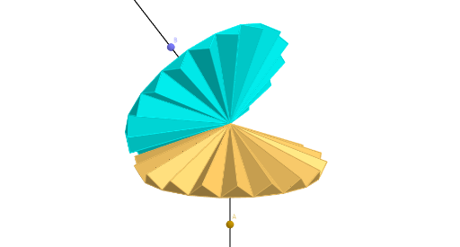
① This GeoGebra example constructs a three-dimensional gear (engrenage 3D) model, demonstrating the meshing motion of two gears under combined rotation and translation transformations, vividly illustrating dynamic constructions in solid geometry. ② Core mathematical concepts include 3D rotation (Rotate), translation (Translate), sequence (Sequence) for generating repeated structures, and the construction of pyramids (Pyramid) and polyhedral faces, involving matrix transformations and composition of geometric transformations. ③ Construction highlights: using Point, PointIn, Ray, AngularBisector to define key points and angle bisectors; applying Rotate and Translate to generate gear tooth arrays; using Pyramid to build the 3D tooth shapes; employing Sequence to batch-create multiple faces (e.g., faceA'CD_1, faceCDO_1) and edges (arêteA'C_1, etc.); and managing repeated elements via lists (liste1, liste2) to complete the full 3D gear structure. ④ Suitable for high school or early college students learning solid geometry, spatial transformations, and parametric modeling, as well as for visualizing gear transmission in mechanical principles, helping to understand the mathematical relationships of rotation direction, meshing angle, and translation distance.
GeoGebra Commands & Parameters
Point(zAxis) → APointIn(Plane[xAxis, zAxis]) → BRay(O, B) → fAngularBisector(A, O, B) → gRotate(A, ((-e) - Angle[A, O, B]) / 2, yAxis) → A'Rotate(Rotate[A, (e - Angle[A, O, B]) / 2, yAxis], π / n, zAxis) → CRotate(Rotate[A, (e - Angle[A, O, B]) / 2, yAxis], ((-π)) / n, zAxis) → DPyramid(A', C, D, O) → pyr1, faceA'CD_1, arêteDO_1, faceA'CO_1, faceCDO_1, faceA'DO_1, arêteA'C_1, arêteCD_1, arêteA'D_1, arêteA'O_1, arêteCO_1Rotate(B, ((-e) + Angle[A, O, B]) / 2, yAxis) → B'Rotate(Rotate[B, (e + Angle[A, O, B]) / 2, yAxis], π / n, f) → ERotate(B', (2 * π / n), f) → B''Pyramid(B', B'', E, O) → pyr2, face1, arête6, face2, face3, face4, arête1, arête2, arête3, arête4, arête5Sequence(Rotate[pyr1, i + d, zAxis], i, 0, (2 * π), (2 * π / n)) → liste1Sequence(Rotate[pyr2, i + d, f], i, 0, (2 * π), (2 * π / n)) → liste2Ray(O, A) → hTranslate(liste2, Vector[(j * Vector[O, B])]) → liste2'
AI Drawing Prompt Reference
Draw a 3D gear meshing model showing the meshing motion of two gears under combined rotation and translation transformations. Define key points and angle bisectors, then generate gear tooth arrays through rotation and translation, construct 3D tooth shapes using pyramids, and batch-create multiple faces and edges with sequences, managing repeated elements via lists to complete the full 3D gear structure.
The prompt above was compiled from the original drawing commands and is for reference only.