
飞行模拟器:双曲线与割线的三维几何演示
几何画板及绘图内容加载中,请稍等……
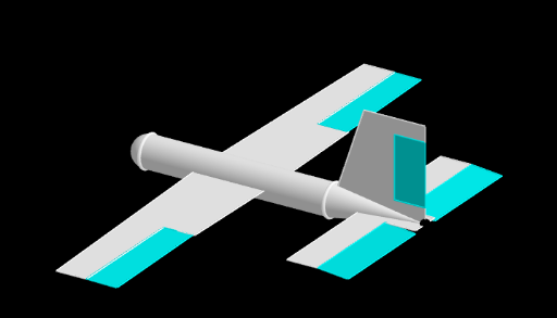
该范例通过一个名为“飞行模拟器”的交互式三维场景,直观演示了双曲线、割线、相似三角形以及矩形与正方形等几何元素在空间中的组合关系。核心数学概念包括双曲线的定义与性质、割线与曲线的交点、相似三角形的比例关系,以及平面图形(矩形、正方形)在三维空间中的构造。作图要点方面,使用了GeoGebra的Point、Cylinder、Cone、Sphere、Polygon、Intersect、Segment、Rotate、PointIn、Line等命令,创建了包括点A、B、C、D、E、F、G、H、I,线段a、b、c、d、e、f、g、h、i、j、k、l、m、n、p、q、r、s、t,以及多边形poly1、poly2、poly3和多个曲面对象(如圆柱、圆锥、球体)在内的复杂几何结构。该范例适合高中或大学低年级学生,用于理解解析几何与立体几何的交叉应用,也可作为数学建模或计算机辅助几何教学的生动案例,帮助学习者将抽象的圆锥曲线概念与直观的三维视觉模拟相结合。
GeoGebra 命令及参数
Point(xAxis) → ACylinder(A, B, 0.5) → a, c, d, bCone(B, C, 0.5) → e, f, gSphere(A, 0.5) → hPolygon(B, (4, 0, 3), (6, 0, 3), (6, 0, 2.5), (5, 0, 2.5), (5, 0, 0.5), (6, 0, 0.5), C, B) → poly1, b_1, i, j, k, l, m, n, c_1, b_2Intersect(k, l) → DIntersect(l, m) → EIntersect(j, k) → FIntersect(n, m) → GPolygon(D, F, G, E, D) → poly2, d_1, f_1, g_1, e_1, d_2Segment(A, B) → pPoint(p) → HPoint(p) → IPolygon(H, (-1, -8), (0, -8), (0, -4), (1, -4), I, H) → poly3, q, r, s, t, a_1, h_1, i_1Intersect(r, s) → JPoint(poly3) → KIntersect(t, s) → LIntersect(t, a_1) → MPolygon(J, M, (1, -8), J) → poly4, j_1, m_1, k_1, j_2Rotate(poly3, 3.141592653589793, xAxis) → poly3'Rotate(poly4, 3.141592653589793, xAxis) → poly4'Polygon(C, (6, -0.5), (5, -0.5), (5, -4), (4, -4), (4, 4), (5, 4), (5, 0.5), (6, 0.5), C) → poly5, c_2, c_3, l_1, n_1, p_1, q_1, r_1, s_1, t_1, a_2Intersect(p_1, n_1) → NPointIn(poly5) → OPolygon(N, O, (6, -0.5), (6, -4), N) → poly6, n_2, o, e_2, f_2, n_3Rotate(poly6, 3.141592653589793, xAxis) → poly6'Rotate(a, up, yAxis) → a'Rotate(e, up, yAxis) → e'Rotate(h, up, yAxis) → h'Rotate(poly3, up, yAxis) → poly3'_1Rotate(poly4, up, yAxis) → poly4'_1Rotate(poly1, up, yAxis) → poly1'Rotate(poly5, up, yAxis) → poly5'Rotate(poly6, up, yAxis) → poly6'_1Rotate(poly2, up, yAxis) → poly2'Rotate(poly3', up, yAxis) → poly3''Rotate(poly4', up, yAxis) → poly4''Rotate(A, up, yAxis) → A'Rotate(B, up, yAxis) → B'Segment(A', B') → p'Rotate(a, ax, p) → a'_1Rotate(poly1, ax, p) → poly1'_1Rotate(poly2, ax, p) → poly2'_1Rotate(poly3, ax, p) → poly3'_2Rotate(poly4, ax, p) → poly4'_2Rotate(poly5, ax, p) → poly5'_1Rotate(poly6, ax, p) → poly6'_2Rotate(h, ax, p) → h'_1Rotate(e, ax, p) → e'_1Rotate(poly3', ax, p) → poly3''_1Rotate(poly4', ax, p) → poly4''_1Rotate(poly6', ax, p) → poly6''Rotate(poly3'_1, ax, p') → poly7Rotate(poly4'_1, ax, p') → poly8Rotate(poly3'', ax, p') → poly3'''Rotate(poly4'', ax, p') → poly4'''Rotate(poly1', ax, p') → poly1''Rotate(poly2', ax, p') → poly2''Rotate(poly5', 3.141592653589793, p') → poly5''Rotate(poly6'_1, ax, p') → poly9Rotate(poly5'', ax, p') → poly5'''Rotate(poly9, 3.141592653589793, p') → poly9'PointIn(poly9) → PPointIn(poly9) → QSegment(P, Q) → g_2Rotate(poly9, (-up), g_2) → poly9'_2PointIn(poly5''') → RPointIn(poly5''') → SSegment(S, R) → h_2Rotate(poly9', up, h_2) → poly9''PointIn(poly1'') → TPointIn(poly2'') → USegment(T, U) → i_2Rotate(poly2'', Rudder, i_2) → poly2'''Rotate(poly9'_2, Elevators, g_2) → poly10Rotate(poly9'', (-Elevators), h_2) → poly9'''Segment(J, L) → k_2PointIn(poly8) → VPolygon(J, L, M, V) → poly11, j_3, l_2, m_2, vRotate(poly11, Ailerons, k_2) → poly11'Rotate(poly11', up, yAxis) → poly11''Rotate(M, up, yAxis) → M'PointIn(poly7) → WPointIn(poly7) → ZLine(W, Z) → p_2PointIn(poly7) → A_1PointIn(poly7) → B_1Point(p_2) → C_1Polygon(Z, A_1, B_1, C_1) → poly12, z_1, a_3, b_3, c_4Rotate(poly12, Ailerons, z_1) → poly12'PointIn(poly3''') → D_1PointIn(poly3''') → E_1Line(D_1, E_1) → q_2PointIn(poly3''') → F_1PointIn(poly3''') → G_1Point(q_2) → H_1Polygon(F_1, E_1, H_1, G_1) → poly13, f_3, e_3, h_3, g_3Rotate(poly13, (-Ailerons), f_3) → poly13'Rotate(h', (-Turn), zAxis) → h''Rotate(poly7, (-Turn), zAxis) → poly7'Rotate(poly11, Turn, zAxis) → poly11'_1Rotate(poly12', (-Turn), zAxis) → poly12''Rotate(poly3''', (-Turn), zAxis) → poly14Rotate(poly13', (-Turn), zAxis) → poly13''Rotate(poly5''', (-Turn), zAxis) → poly15Rotate(poly10, (-Turn), zAxis) → poly10'Rotate(poly9''', (-Turn), zAxis) → poly16Rotate(poly1'', (-Turn), zAxis) → poly1'''Rotate(poly2''', (-Turn), zAxis) → poly17Rotate(a', (-Turn), zAxis) → a''Rotate(e', (-Turn), zAxis) → e''PointIn(poly1''') → I_1PointIn(poly17) → J_1Segment(I_1, J_1) → r_2Rotate(poly17, (-Turn), r_2) → poly17'Rotate(A', Turn, zAxis) → A''Rotate(B', Turn, zAxis) → B''Rotate(A', (-Turn), zAxis) → A''_1Rotate(B', (-Turn), zAxis) → B''_1Segment(A''_1, B''_1) → p''Rotate(h'', (-Turn2), zAxis) → h'''Rotate(a'', (-Turn2), zAxis) → a'''Rotate(e'', (-Turn2), zAxis) → e'''Rotate(poly1''', (-Turn2), zAxis) → poly18Rotate(poly17', (-Turn2), zAxis) → poly17''Rotate(poly15, (-Turn2), zAxis) → poly15'Rotate(poly10', (-Turn2), zAxis) → poly10''Rotate(poly16, (-Turn2), zAxis) → poly16'Rotate(poly7', (-Turn2), zAxis) → poly7''Rotate(poly12'', (-Turn2), zAxis) → poly12'''Rotate(poly14, (-Turn2), zAxis) → poly14'Rotate(poly12'', (-Turn2), zAxis) → poly12'''_1Rotate(poly13'', (-Turn2), zAxis) → poly13'''PointIn(poly12'''_1) → K_1PointIn(poly12''') → L_1Segment(K_1, L_1) → s_2Rotate(poly12''', Turn2, s_2) → poly19PointIn(poly14') → M_1PointIn(poly13''') → N_1Segment(M_1, N_1) → t_2Rotate(poly13''', (-Turn2), t_2) → poly20Rotate(poly13''', (-Turn2), t_2) → poly21PointIn(h''') → O_1PointIn(poly18) → P_1Segment(O_1, P_1) → d_3Rotate(poly7'', (-Turn2), d_3) → poly7'''Rotate(poly19, (-Turn2), d_3) → poly19'Rotate(poly14', (-Turn2), d_3) → poly14''Rotate(poly20, (-Turn2), d_2) → poly20'Rotate(poly20', (-Turn2), d_2) → poly20''Rotate(poly18, (-Turn2), d_2) → poly18'Rotate(poly18, (-Turn2), d_3) → poly18'_1PointIn(poly14'') → Q_1PointIn(poly14') → R_1Rotate(poly17'', (-Turn2), d_3) → poly17'''Rotate(poly20', (-Turn2), d_3) → poly20''_1Rotate(poly15', (-Turn2), d_3) → poly15''Rotate(poly10'', (-Turn2), d_3) → poly10'''Rotate(poly20''_1, (-Turn2), d_3) → poly22Rotate(poly16', (-Turn2), d_3) → poly16''PointIn(poly14'') → S_1PointIn(poly14'') → T_1Line(S_1, T_1) → i_3PointIn(poly14'') → V_1PointIn(poly14'') → W_1Point(i_3) → Z_1Polygon(V_1, W_1, Z_1, T_1) → poly23, v_1, w_1, z_2, t_3Rotate(poly23, Ailerons, t_3) → poly23'Rotate(poly23, Turn2, t_3) → poly23'_1Rotate(poly23', Turn2, t_3) → poly23''PointIn(poly7''') → A_2PointIn(poly19') → B_2Segment(B_2, A_2) → k_3Rotate(poly19', (0.6 * ax), k_3) → poly19''PointIn(poly18'_1) → C_2PointIn(poly17''') → D_2Segment(C_2, D_2) → l_3Rotate(poly17''', (-0.6 * ax), l_3) → poly24PointIn(poly14'') → E_2PointIn(poly14'') → F_2Segment(E_2, F_2) → m_3Segment(E_2, F_2) → p_3Rotate(poly23'', (0.6 * ax), m_3) → poly23'''
AI 绘图提示语参考
绘制一个三维几何场景,包含一条水平轴上的圆柱、圆锥和球体,以及多个多边形平面。在空间中构造双曲线与割线,通过交点形成相似三角形和矩形。沿轴旋转这些平面,并围绕垂直轴和另一条线段进行旋转复制,生成对称的立体组合。整体呈现飞行模拟器的视觉效果,展示圆锥曲线与立体几何的交互关系。
以上提示语为根据原始绘图命令整理而来,仅供参考。