
五球牛顿摆:对称碰撞与轨迹几何仿真
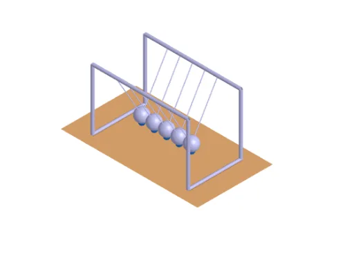
几何画板及绘图内容加载中,请稍等……
该范例演示由五个相同自由球组成的牛顿摆在摆动与碰撞下的运动过程,并可通过滑块改变初始拉开角度与长度等参数观察对称性与能量交换的“轨迹规律”。核心数学概念包括圆周与弦相关的几何关系、角度测量、碰撞时的对称/对应位置刻画,以及用三角角度参数化轨迹(如摆角θ与φ)来控制各球的动态位置。构造要点:利用GeoGebra 的 Line、Point、Angle、Intersect、Polygon、Cylinder、Sphere、CircumcircleArc 与 If 实现摆线/连接线、关键点、角度标定、几何求交、外形轮廓与立体球体(Cylinder/Sphere)渲染;再通过多个参数对象与控制量(如 lengthController、widthController、heightController、pullRadius、pendulumRadius、trajectoryRadius、g)以及动态位置(dynamicPosition_i、pullPoint_i、restPosition、trajectoryCenter_i 等)生成并切换各球的轨迹中心与拉回位置。适合中学高年级到大学的数学建模、几何作图与参数化动画教学,也适合作为课堂演示的可视化实验。
GeoGebra 命令及参数
Line(basePoint, zAxis) → jPoint(j) → heightControllerLine(basePoint, yAxis) → gPoint(g) → widthControllerLine(basePoint, xAxis) → fPoint(f) → lengthControllerCircumcircleArc(trajectoryCenter_{3} + ((-pullRadius), 0, 0), trajectoryCenter_{3} + (0, 0, (-pullRadius)), trajectoryCenter_{3} + (pullRadius, 0, 0)) → e_2Point(e_2) → pullPoint_{3}Angle(pullPoint_{3}, trajectoryCenter_{3}, trajectoryCenter_{3} + restPosition, yAxis) → θ_{i}CircumcircleArc(trajectoryCenter_{4} + ((-pullRadius), 0, 0), trajectoryCenter_{4} + (0, 0, (-pullRadius)), trajectoryCenter_{4} + (pullRadius, 0, 0)) → r_2Point(r_2) → pullPoint_{4}Angle(pullPoint_{4}, trajectoryCenter_{4}, trajectoryCenter_{4} + restPosition, yAxis) → φ_{i}CircumcircleArc(trajectoryCenter_{2} + ((-pullRadius), 0, 0), trajectoryCenter_{2} + (0, 0, (-pullRadius)), trajectoryCenter_{2} + (pullRadius, 0, 0)) → d_2Point(d_2) → pullPoint_{2}CircumcircleArc(trajectoryCenter_{1} + ((-pullRadius), 0, 0), trajectoryCenter_{1} + (0, 0, (-pullRadius)), trajectoryCenter_{1} + (pullRadius, 0, 0)) → c_2Point(c_2) → pullPoint_{1}Angle(pullPoint_{1}, trajectoryCenter_{1}, trajectoryCenter_{1} + restPosition, yAxis) → γ_{i}CircumcircleArc(trajectoryCenter_{5} + ((-pullRadius), 0, 0), trajectoryCenter_{5} + (0, 0, (-pullRadius)), trajectoryCenter_{5} + (pullRadius, 0, 0)) → s_2Point(s_2) → pullPoint_{5}Angle(pullPoint_{5}, trajectoryCenter_{5}, trajectoryCenter_{5} + restPosition, yAxis) → ω_{i}Angle(pullPoint_{2}, trajectoryCenter_{2}, trajectoryCenter_{2} + restPosition, yAxis) → δ_{i}Line(widthController, f) → hLine(lengthController, g) → iIntersect(i, h) → DPolygon(basePoint, lengthController, D, widthController) → q1, a, b, d, cCylinder(J, K, cylinderRadius) → e, k, p, lCylinder(M, L, cylinderRadius) → m, q, r, nCylinder(H, J, cylinderRadius) → o, s, t, uCylinder(F, K, cylinderRadius) → v, c_1, d_1, wCylinder(E, L, cylinderRadius) → a_1, e_1, f_1, b_1Cylinder(G, M, cylinderRadius) → g_1, g_2, g_3, g_4Cylinder(F, E, cylinderRadius) → h_1, k_1, p_1, i_1Cylinder(G, H, cylinderRadius) → j_1, q_1, r_1, l_1If(time ≤ π / 2, trajectoryCenter_{1} + dynamicPosition_{1}, trajectoryCenter_{1} + dynamicPosition_{5}) → sphereCenter_{1}Segment(U, sphereCenter_{1}) → f_2Segment(sphereCenter_{1}, V) → h_2If(time ≤ π / 2, trajectoryCenter_{2} + dynamicPosition_{2}, trajectoryCenter_{2} + dynamicPosition_{4}) → sphereCenter_{2}Segment(Z, sphereCenter_{2}) → i_2Segment(sphereCenter_{2}, W) → j_2Segment(sphereCenter_{3}, A_1) → k_2Segment(sphereCenter_{3}, B_1) → l_2If(time ≤ π / 2, trajectoryCenter_{4} + dynamicPosition_{4}, trajectoryCenter_{4} + dynamicPosition_{2}) → sphereCenter_{4}Segment(D_1, sphereCenter_{4}) → m_2Segment(sphereCenter_{4}, C_1) → n_2If(time ≤ π / 2, trajectoryCenter_{5} + dynamicPosition_{5}, trajectoryCenter_{5} + dynamicPosition_{1}) → sphereCenter_{5}Segment(E_1, sphereCenter_{5}) → p_2Segment(sphereCenter_{5}, F_1) → q_2Sphere(sphereCenter_{1}, sphereRadius) → m_1Sphere(sphereCenter_{2}, sphereRadius) → n_1Sphere(sphereCenter_{3}, sphereRadius) → o_1Sphere(sphereCenter_{4}, sphereRadius) → s_1Sphere(sphereCenter_{5}, sphereRadius) → t_1
AI 绘图提示语参考
请绘制一个展示五个球牛顿摆球的图形,呈现对称碰撞和几何轨迹。图形应包含五个球体,每个球体通过连接线与轨迹中心相连,轨迹中心呈对称分布。需画出球体碰撞后的运动路径,体现角度和参数控制。构造顺序为:先确定轨迹中心,再绘制球体,最后连接各球体与轨迹中心。整体应保持对称性,展示几何关系与动态轨迹。
以上提示语为根据原始绘图命令整理而来,仅供参考。