
立体变换:Cube与八面体转Cuboctahedron
几何画板及绘图内容加载中,请稍等……
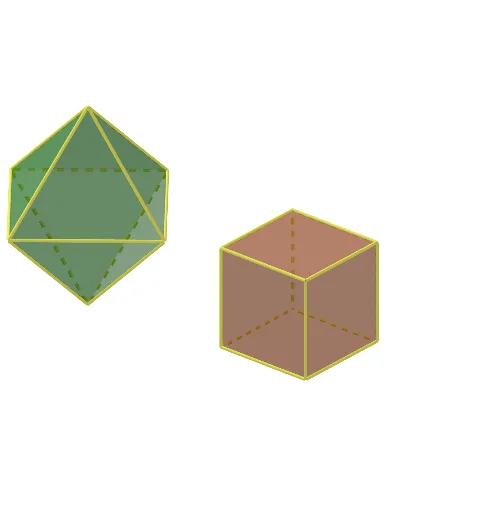
该applet演示如何通过几何变换,将正方体和正八面体转化为相同的Cuboctahedron(半正多面体)。核心数学概念包括多面体变换、对称性与几何重构。作图要点涉及Point、Segment、Polygon、Prism、Pyramid、Sphere、Intersect、Midpoint、Line及Rotate等GeoGebra命令,通过顶点、边和面的交互构建转化过程。适合高中及以上立体几何、解析几何或变换几何单元,帮助学生直观理解多面体的相互转化与对称性。
GeoGebra 命令及参数
Point(Circle[A, (2 * sqrt(2))]) → BSegment(A, B) → fPolygon(A, B, 4) → poly1, g, h, i, j, C, DPolygon(E, F, 4, xOyPlane) → poly2, k, l, m, n, G, HPrism(poly2, b) → c, M, edgeEM, edgeFN, edgeGO, edgeHP, edgeMN, edgeNO, edgeOP, edgeMP, N, O, P, faceEFNM, faceFGON, faceGHPO, faceEHPM, faceMNOPPolygon(A, B, 4) → poly3, p, q, r, s, I, JPyramid(poly3, e) → o, L, faceABL, faceBIL, faceIJL, faceAJL, edgeAL, edgeBL, edgeIL, edgeJLPyramid(poly3, t) → u, Q, faceABQ, faceBIQ, faceIJQ, faceAJQ, edgeAQ, edgeBQ, edgeIQ, edgeJQSphere(M, a) → vIntersect(edgeGO, v) → K,Intersect(edgeMN, v, 1) → RIntersect(edgeEM, v, 1) → SIntersect(edgeMP, v, 1) → TPolygon(T, S, R) → t1, r_1, t_1, s_1Midpoint(M, O) → UMidpoint(E, G) → VLine(U, V) → f_1Rotate(t1, (-(90°)), f_1) → t1'Rotate(R, (-(90°)), f_1) → R'Rotate(T, (-(90°)), f_1) → T'Rotate(S, (-(90°)), f_1) → S'Rotate(t1, (-(180°)), f_1) → t1'_1Rotate(R, (-(180°)), f_1) → R'_1Rotate(T, (-(180°)), f_1) → T'_1Rotate(S, (-(180°)), f_1) → S'_1Rotate(t1, (-(270°)), f_1) → t1'_2Rotate(R, (-(270°)), f_1) → R'_2Rotate(T, (-(270°)), f_1) → T'_2Rotate(S, (-(270°)), f_1) → S'_2Segment(H, E) → g_1Segment(E, F) → h_1Segment(F, G) → i_1Segment(H, G) → j_1Sphere(E, a) → wIntersect(h_1, w, 1) → WIntersect(edgeEM, w, 1) → ZIntersect(g_1, w, 1) → A_1Polygon(Z, A_1, W) → t2, w_1, z_1, a_1Rotate(t2, (-(90°)), f_1) → t2'Rotate(Z, (-(90°)), f_1) → Z'Rotate(W, (-(90°)), f_1) → W'Rotate(A_1, (-(90°)), f_1) → B_1Rotate(t2, (-(180°)), f_1) → t2'_1Rotate(W, (-(180°)), f_1) → W'_1Rotate(A_1, (-(180°)), f_1) → C_1Rotate(Z, (-(180°)), f_1) → Z'_1Rotate(t2, (-(270°)), f_1) → t2'_2Rotate(Z, (-(270°)), f_1) → Z'_2Rotate(A_1, (-(270°)), f_1) → D_1Rotate(W, (-(270°)), f_1) → W'_2Sphere(L, ((a * 2) * sqrt(2) / 2)) → b_1Intersect(edgeIL, b_1, 1) → E_1Intersect(edgeBL, b_1, 1) → F_1Intersect(edgeJL, b_1, 1) → G_1Intersect(edgeAL, b_1, 1) → H_1Polygon(H_1, F_1, E_1, G_1) → q1, k_1, l_1, e_1, m_1Sphere(A, (a * sqrt(2))) → c_1Intersect(edgeAL, c_1, 1) → I_1Intersect(p, c_1, 1) → J_1Intersect(s, c_1, 1) → K_1Intersect(edgeAQ, c_1, 1) → L_1Polygon(K_1, L_1, J_1, I_1) → q2, n_1, p_1, q_1, d_1Line(L, Q) → f_2Rotate(q2, (-(90°)), f_2) → q2'Rotate(K_1, (-(90°)), f_2) → M_1Rotate(I_1, (-(90°)), f_2) → N_1Rotate(J_1, (-(90°)), f_2) → O_1Rotate(L_1, (-(90°)), f_2) → P_1Rotate(q2, (-(180°)), f_2) → q2'_1Rotate(K_1, (-(180°)), f_2) → Q_1Rotate(I_1, (-(180°)), f_2) → R_1Rotate(J_1, (-(180°)), f_2) → S_1Rotate(L_1, (-(180°)), f_2) → T_1Rotate(q2, (-(270°)), f_2) → q2'_2Rotate(J_1, (-(270°)), f_2) → U_1Rotate(K_1, (-(270°)), f_2) → V_1Rotate(L_1, (-(270°)), f_2) → W_1Rotate(I_1, (-(270°)), f_2) → Z_1Line(J, B) → g_2Rotate(q1, 180°, g_2) → q1'Rotate(F_1, 180°, g_2) → A_2Rotate(E_1, 180°, g_2) → B_2Rotate(H_1, 180°, g_2) → C_2Rotate(G_1, 180°, g_2) → D_2Polygon(R_1, S_1, V_1, Z_1, G_1, E_1) → poly4, s_2, t_2, v_1, a_2, b_2, c_2Polygon(Z_1, U_1, K_1, I_1, H_1, G_1) → poly5, h_2, u_1, i_2, j_2, d_2, e_2Polygon(H_1, I_1, J_1, M_1, N_1, F_1) → poly6, k_2, l_2, m_2, n_2, f_3, g_3Polygon(O_1, P_1, A_2, C_2, T_1, Q_1) → poly7, h_3, i_3, j_3, k_3, l_3, m_3Polygon(S_1, T_1, C_2, D_2, W_1, V_1) → poly8, n_3, p_3, q_3, r_3, s_3, t_3Polygon(U_1, W_1, D_2, B_2, L_1, K_1) → poly9, a_3, b_3, c_3, d_3, e_3, f_4Polygon(R', T'_1, R'_1, T'_2, R'_2, T, R, T') → poly10, r', t'_1, r'_1, t'_2, r'_2, t_4, r_4, t'Polygon(R, S, Z, W, B_1, Z', S', T') → poly11, r_5, s_4, z_2, w_2, g_4, z', s', h_4Polygon(R', S', Z', W', C_1, Z'_1, S'_1, T'_1) → poly12, i_4, j_4, k_4, w', l_4, z'_1, s'_1, m_4Polygon(R'_1, S'_1, Z'_1, W'_1, D_1, Z'_2, S'_2, T'_2) → poly13, n_4, p_4, q_4, w'_1, a_4, z'_2, s'_2, b_4Polygon(R'_2, S'_2, Z'_2, W'_2, A_1, Z, S, T) → poly14, c_4, d_4, e_4, w'_2, f_5, z_3, s_5, t_5Polygon(A_1, W'_2, D_1, W'_1, C_1, W', B_1, W) → poly15, g_5, h_5, i_5, j_5, k_5, l_5, m_5, w_3Polygon(E_1, R_1, Q_1, O_1, N_1, F_1) → poly16, p_2, q_2, r_2, o_1, n_5, p_5Polygon(I_1, K_1, L_1, J_1) → q3, q_5, a_5, b_5, c_5Polygon(A_2, B_2, D_2, C_2) → q4, d_5, e_5, f_6, g_6Polygon(M_1, B_2, A_2) → t3, h_6, i_6, j_6
AI 绘图提示语参考
画一个立方体和一个正八面体,展示它们如何通过几何变换形成一个截角立方体。首先画出立方体的顶点和边,再画出正八面体的顶点和边。接着,将正八面体沿其中心垂直向上延伸形成八棱柱。然后,将立方体的每个面延伸并截去顶点,形成截角立方体的雏形。最后,在八棱柱的顶点处画上球体,并将截角立方体的顶点处也画上球体,使图形更加饱满。
以上提示语为根据原始绘图命令整理而来,仅供参考。