
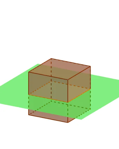
立方体的截面演示
几何画板及绘图内容加载中,请稍等……
所属专题
intersection: surface-surface, curve-curve
intersection: surface-surface, curve-curve
intersection: surface-surface, curve-curve
intersection: surface-surface, curve-curve
① 该范例演示立方体被平面切割时形成的各种截面形状。② 涉及立体几何、截面多边形、空间变换与平面交线等核心概念。③ 作图使用了 Point、Cube、Translate、IntersectPath 等命令,构造了顶点 A、B、C…、面 face1‑face4、边 edge1‑edge5、参数 shift、tilt、turn 以及多边形 poly1 等对象。④ 适合高中立体几何教学、几何作图训练及 GeoGebra 进阶动画演示。
GeoGebra 命令及参数
Point(Circle[(2, -2, -2), Distance[(-2, -2, -2), (2, -2, -2)], Segment[(-2, -2, -2), (2, -2, -2)]]) → ACube((-2, -2, -2), (2, -2, -2), A) → a, B, faceABFE, faceCDEF, edge2, edge1, edge4, edgeAB, edge3, edgeBF, edgeCF, edgeCD, C, edge5, edgeDE, edgeAE, edgeEF, D, E, F, face1, face3, face2, face4Translate(Rotate[Rotate[Plane[(0, 1, 0), xAxis], tilt, xAxis], turn, zAxis], Vector[(0, 0, shift)]) → bIntersectPath(b, a) → poly1, G, i, j, k, H, I, J, K, L, f, g, h
AI 绘图提示语参考
绘制一个立方体的截面图形。立方体由六个顶点、多个面和边组成。平面通过参数shift、tilt和turn进行平移和旋转,与立方体相交形成多边形截面。构造顺序为:先定义一个点,然后创建立方体,接着应用平移和旋转,最后计算平面与立方体的交线得到截面多边形。
以上提示语为根据原始绘图命令整理而来,仅供参考。