
Web Quest Lift-Rod Problem: Solid Geometry Construction with Prisms and Distance
Loading the math board and drawing, please wait…
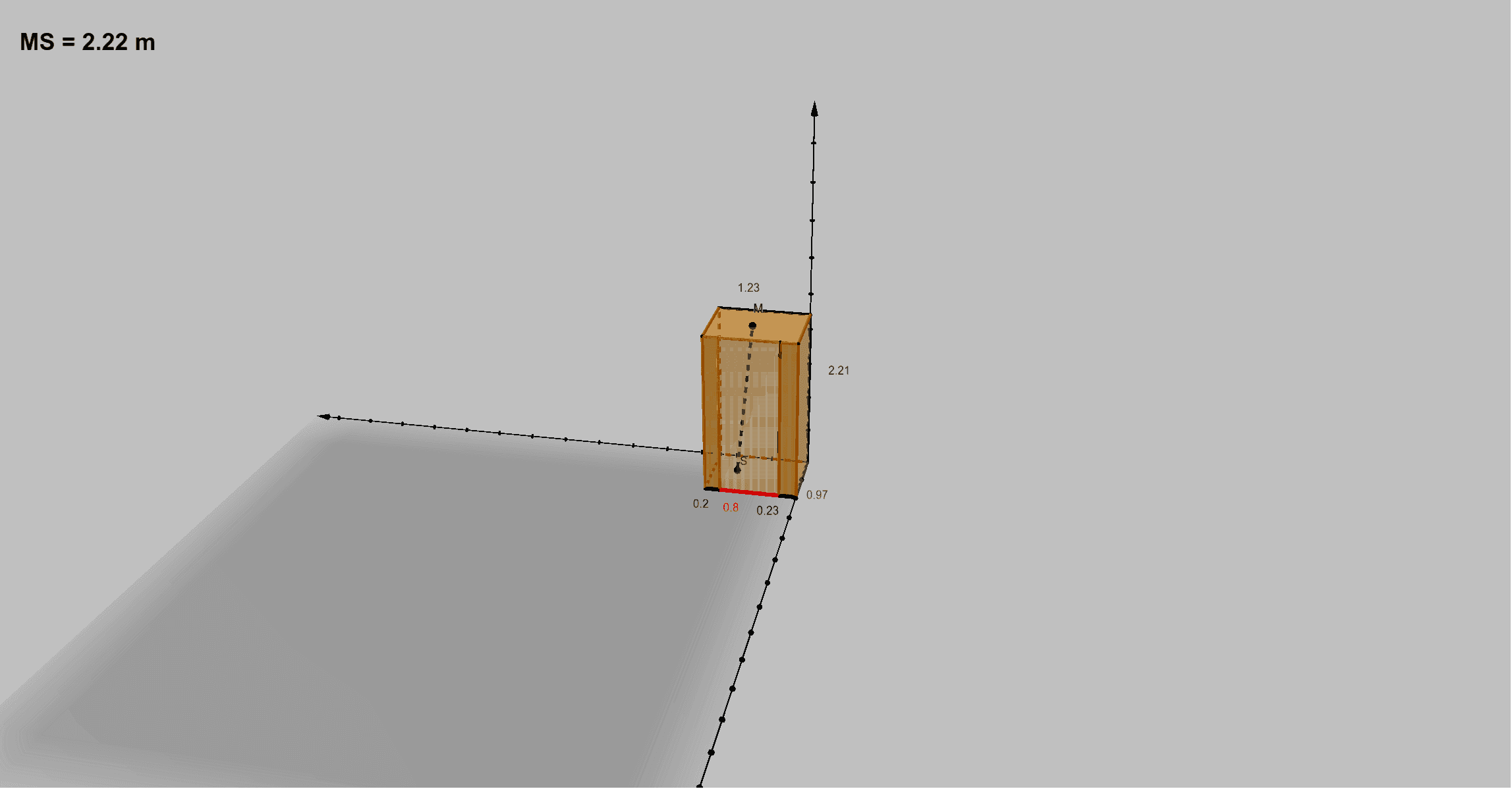
This example visualizes a Lift-Rod–style geometric constraint in 3D by building a solid model and using geometric predicates and measurements. Students can observe how a rod/segment relationship is governed by spatial configuration when key points move or parameters change.
It centers on solid geometry and measurement: defining a cuboid/prism-like structure, constructing faces and edges, and enforcing constraints using distances between points.
Construction approach (from the build summary): Polygon to form face outlines (e.g., faceABHG, faceBFIH, faceCFIJ, faceACJG), Prism to generate the main 3D body, PointIn to test whether a point lies inside a given region, Distance to compute the metric quantities used for constraints, and Segment to represent rods/edges (e.g., edgeAG, edgeBH, edgeFI, edgeCJ, edgeGH, edgeHI, edgeIJ, edgeGJ).
Suitable for upper secondary and early university students studying 3D geometry, geometric construction, and model-based exploration (including Web Quest activities).
GeoGebra Commands & Parameters
Polygon(A, B, F, C) → q1, a, b, f, cPrism(q1, G) → d, H, edgeBH, edgeFI, edgeCJ, edgeGH, edgeHI, edgeIJ, edgeGJ, I, J, faceABHG, faceBFIH, faceCFIJ, faceACJG, faceGHIJ, edgeAGPolygon(J, K, D, C) → q2, j, k, d_1, c_1Polygon(L, I, F, E) → q3, l, i, f_1, ePolygon(K, L, E, D) → q4, k_1, l_1, e_1, d_2PointIn(faceGHIJ) → MPointIn(q1) → SDistance(M, S) → d6Segment(M, S) → MS
AI Drawing Prompt Reference
Draw a 3D solid model generated by a prism. The model includes multiple faces and edges, such as faces ABHG, BFIH, CFIJ, and ACJG, and edges AG, BH, FI, CJ, GH, HI, IJ, and GJ. The construction order is to first define the polygon outlines of these faces, then generate the prism body, add other faces, and finally calculate the distance between key points to show the rod segment relationship.
The prompt above was compiled from the original drawing commands and is for reference only.