
Visualizing an Infinite Limit of a Function at a Point
Loading the math board and drawing, please wait…
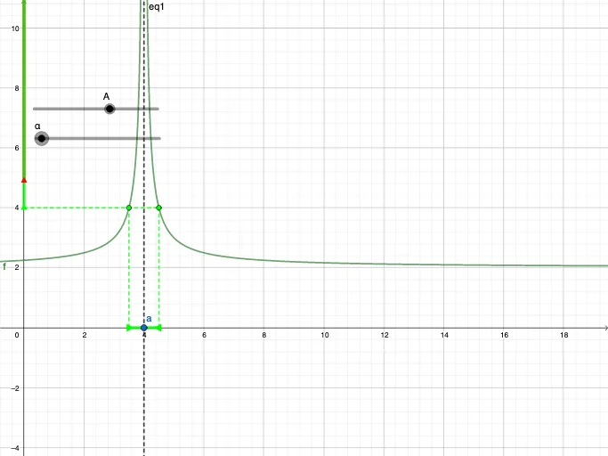
This GeoGebra example demonstrates the phenomenon of an infinite (diverging) limit: as the input approaches a specific point, the function values grow without bound, producing a clear visual “blow-up” behavior. The key math concepts are limits (infinite limits) and the asymptotic nature of a function near a point, supported by coordinated geometric construction. In the construction, GeoGebra commands such as Point and Segment are used to place crucial reference points and draw auxiliary segments. Function-related objects (e.g., f and g) together with parameters (e.g., a, alpha) define the approach point and the viewing direction. Additional geometric entities (A, B, C, D, h, i, F, l, BigA, p, G) and an equation/expression object (e.g., eq1) are used to organize constraints and encode the functional relationship, so the graph near the target point clearly indicates divergence. Suitable for secondary school to early university students studying limits and function graphs, especially for classroom visualization and self-study.
GeoGebra Commands & Parameters
Point(xAxis) → aSegment((4 - alpha, 0), (4 + alpha, 0)) → gPoint(g) → APoint(g) → BSegment(A, C) → hSegment(B, D) → iSegment(F, D) → lSegment((0, BigA), (0, 100)) → pSegment(F, (0, 100)) → j
AI Drawing Prompt Reference
Create a diagram visualizing an infinite (diverging) limit of a function at a point. Start by choosing a central reference point on the x-axis that the input will approach, and draw a symmetric horizontal segment around it to mark the observation interval. Then use the segment’s endpoints to place auxiliary points and connect them with additional line segments upward/downward or diagonally, linking to other key auxiliary points already set for the construction. Next, draw a vertical reference segment reaching from a high y-level down to the same central axis location, and connect this vertical segment to a previously defined critical point with another segment. Arrange the resulting geometric layout to clearly suggest a “blow-up” behavior of the function near the target point, using the approach direction implied by the auxiliary construction.
The prompt above was compiled from the original drawing commands and is for reference only.