
Step-by-step Construction of the Sri-Yantra
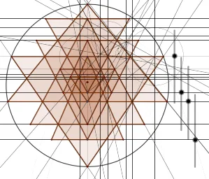
Loading the math board and drawing, please wait…
This example demonstrates how to construct the key symmetrical structure of the Sri-Yantra pattern on a plane using a precise sequence of geometric construction steps. The main mathematical ideas include: constructing points and lines (lines, rays, segments), creating and using circles and semicircles for curved constraints, determining new vertices via intersections, using midpoint to establish controlled symmetry, building perpendicular (orthogonal) relations, and generating invariances through mirror symmetry, line bisectors, and angular bisectors. The construction workflow is implemented with GeoGebra commands such as Intersect, Point, Semicircle, Line, OrthogonalLine, Ray, Segment, Midpoint, Circle, Parabola, Mirror, LineBisector, AngularBisector, and Polygon. It is well suited for geometry-construction instruction, math clubs, and competition-style learning, especially for students who want to connect elementary Euclidean constructions with algorithmic dynamic geometry modeling.
GeoGebra Commands & Parameters
Intersect(xAxis, yAxis) → APoint(yAxis) → BSemicircle(B, A) → c_6Semicircle(A, B) → d_3Line(B, A) → fOrthogonalLine(C, f) → gOrthogonalLine(E, f) → hIntersect(c_6, g, 1) → GIntersect(c_6, h, 1) → HLine(B, H) → iLine(A, G) → jIntersect(d_3, g, 1) → ILine(A, I) → kIntersect(d_3, h, 1) → JLine(B, J) → lIntersect(g, i) → KOrthogonalLine(D, f) → qIntersect(h, j) → QIntersect(f, yAxis) → Q_1Ray(F, K) → mIntersect(h, m) → LRay(C, L) → nIntersect(j, n) → MOrthogonalLine(M, f) → pIntersect(f, p) → NIntersect(q, n) → ORay(N, O) → rSegment(D, K) → sIntersect(q, m) → PSegment(P, C) → tIntersect(s, t) → RRay(B, R) → a_7Intersect(g, a_7) → SIntersect(g, r) → TLine(D, a_7) → f_1Line(Q, r) → g_1Intersect(f_1, g) → UIntersect(g_1, g) → VMidpoint(D, C) → WOrthogonalLine(Q, g) → b_7Intersect(g, b_7) → ZMidpoint(Z, Q) → A_1OrthogonalLine(A_1, b_7) → eOrthogonalLine(W, f) → h_1OrthogonalLine(U, g) → i_1OrthogonalLine(V, g) → j_1Midpoint(U, T) → B_1Midpoint(S, V) → C_1OrthogonalLine(B_1, g) → k_1OrthogonalLine(C_1, g) → l_1Intersect(k_1, h_1) → F_1Intersect(l_1, e) → G_1Segment(G_1, V) → m_1Segment(U, F_1) → n_1Midpoint(U, F_1) → H_1Midpoint(G_1, V) → I_1OrthogonalLine(I_1, m_1) → p_1OrthogonalLine(H_1, n_1) → q_1Intersect(k_1, q_1) → J_1Intersect(p_1, l_1) → K_1Intersect(p_1, j_1) → L_1Intersect(i_1, q_1) → M_1Intersect(e, j_1) → E_1Circle(V, L_1) → c_1Intersect(c_1, j_1) → D_1, N_1Intersect(g, f_1) → O_1Circle(U, M_1) → d_1Intersect(d_1, i_1) → P_1, R_1OrthogonalLine(R_1, i_1) → r_1OrthogonalLine(N_1, j_1) → s_1Parabola(K_1, s_1) → e_1Parabola(J_1, r_1) → t_1Intersect(t_1, e_1) → S_1, T_1, ,OrthogonalLine(S_1, g) → a_1Intersect(a_1, g) → U_1OrthogonalLine(T_1, h_1) → b_1Intersect(k_1, r_1) → V_1Intersect(k_1, s_1) → W_1Line(V_1, K_1) → f_2Line(W_1, f_2) → g_2Intersect(l_1, g_2) → Z_1Circle(K_1, Z_1) → c_2Intersect(c_2, l_1) → A_2, B_2Segment(J_1, Z_1) → h_2Line(J_1, B_2) → i_2Intersect(l_1, r_1) → C_2Circle(J_1, Z_1, C_2) → d_2Intersect(d_2, i_2) → D_2, E_2Intersect(c_2, d_2) → F_2, G_2, ,Line(Z_1, G_2) → j_2Intersect(j_2, i_2) → H_2Semicircle(K_1, H_2) → e_2Semicircle(H_2, K_1) → k_2Intersect(c_2, k_2) → I_2, M_3, ,Circle(J_1, E_2, I_2) → p_2Ray(D, U_1) → l_2Intersect(i, l_2) → J_2OrthogonalLine(J_2, f) → m_2Intersect(m_2, f) → K_2Segment(K_2, P) → n_2Intersect(l_2, a_7) → L_2OrthogonalLine(L_2, f) → q_2Intersect(j_2, r) → M_2Intersect(r, q_2) → N_2Ray(Q, N_2) → r_2Intersect(l_2, r_2) → O_2Intersect(r_2, f) → P_2OrthogonalLine(P_2, f) → s_2Intersect(i, s_2) → Q_2Intersect(s_2, l_2) → R_2OrthogonalLine(F, f) → t_2Line(P_2, Q) → a_2Intersect(p, a_2) → S_2Intersect(t_2, n) → T_2Intersect(j, t_2) → U_2Intersect(i, j) → V_2Intersect(m, m_2) → W_2Intersect(n, l_2) → Z_2OrthogonalLine(Z_2, f) → b_2Intersect(n_2, b_2) → A_3Mirror(T_2, f) → B_3Mirror(S_2, f) → C_3Mirror(W_2, f) → D_3Mirror(R_2, f) → E_3Mirror(A_3, f) → F_3Mirror(L_2, f) → G_3Mirror(N_2, f) → H_3Mirror(P, f) → P'Midpoint(D, Z_2) → I_3LineBisector(D, Z_2) → l_7Intersect(l_7, f) → J_3AngularBisector(b_2, l_2) → g_3, h_3Intersect(g_3, f) → K_3Segment(A_3, E) → i_3Segment(E, H) → j_3Segment(H, B) → k_3Semicircle(B, A) → c_3Segment(A, G) → l_3Segment(G, C) → m_3Segment(C, T_2) → n_3Segment(T_2, F) → p_3Segment(F, W_2) → q_3Segment(W_2, K_2) → r_3Segment(K_2, P) → s_3Segment(P, D) → t_3Segment(D, R_2) → a_3Segment(R_2, P_2) → b_3Segment(P_2, S_2) → f_4Segment(S_2, N) → g_4Segment(N, N_2) → h_4Segment(N_2, H_3) → i_4Segment(H_3, N) → j_4Segment(N, C_3) → k_4Segment(C_3, P_2) → l_4Segment(P_2, E_3) → m_4Segment(E_3, D) → n_4Segment(D, P') → p_4Segment(P', K_2) → q_4Segment(K_2, D_3) → r_4Segment(D_3, F) → s_4Segment(F, B_3) → t_4Segment(B_3, C) → a_4Segment(C, I) → b_4Segment(I, A) → c_4Semicircle(A, B) → d_4Segment(B, J) → e_4Segment(J, E) → f_5Segment(E, F_3) → g_5Segment(F_3, A_3) → h_5Polygon(F_3, E, A_3) → t2, i_5, j_5, e_5Polygon(K_2, P', P) → t3, p_5, k_5, p'Polygon(H_3, N_2, N) → t4, n_5, l_5, m_5Polygon(C, B_3, T_2) → t5, q_5, c_5, r_5Polygon(E_3, D, R_2) → t6, s_5, t_5, d_5Polygon(P_2, C_3, S_2) → t7, a_5, b_5, f_6Polygon(D_3, F, W_2) → t8, w_2, g_6, f_7Polygon(B, J, H) → t9, h_6, b_6, j_6Polygon(I, G, A) → t10, a_6, i_6, g_7Intersect(g_3, f) → L_3
AI Drawing Prompt Reference
Draw a symmetric geometric figure with two circular arcs and a straight line. The arcs' endpoints are the intersection points of the line. The line intersects the arcs, and perpendicular lines to the line intersect the arcs to create new points. Connect these points with line segments, and use perpendicular lines to intersect the line. Finally, form a closed figure using these segments and perpendicular lines. The figure should maintain symmetry and have clear lines.
The prompt above was compiled from the original drawing commands and is for reference only.