
Square Pyramid: Internal Structure Analysis
Loading the math board and drawing, please wait…
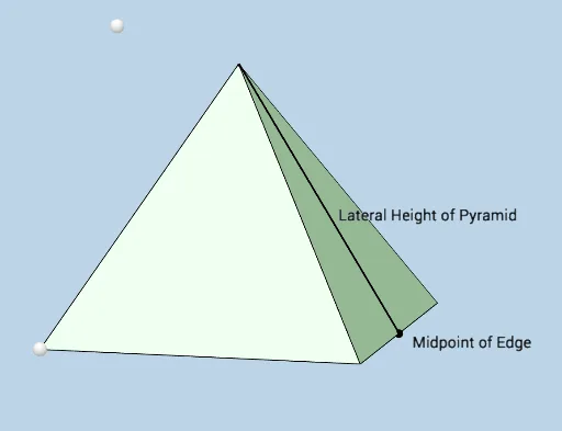
This interactive GeoGebra applet demonstrates the complete internal structure of a regular square pyramid, including all geometric elements such as the base, lateral faces, edges, vertices, and diagonals. Core mathematical concepts involve solid geometry of pyramids, vertical relationships between planes and spaces, properties of squares and right triangles, and applications of the Pythagorean theorem in three-dimensional space. Construction highlights: Using Pyramid command to create the pyramid, Intersect for intersection lines, Polygon for drawing faces, Angle for dihedral angle measurement, and OrthogonalLine for perpendicular lines. Objects include base vertices A, B, C, D, apex E/F, along with edge and face markers. Suitable for secondary school solid geometry units, demonstrating pyramid composition, exploring geometric properties, or as an introduction to spatial vectors and 3D coordinates.
GeoGebra Commands & Parameters
Intersect(yAxis, xAxis) → DPoint(zAxis) → EPointIn(c) → FPyramid(D, A, C, B, F) → b, faceACBD_1, edgeDF, edgeAF, edgeCF, edgeBF, faceADF, faceACF, faceBCF, faceBDF, edgeAD_1, edgeAC_1, edgeBC_1, edgeBD_1Ray(G, H) → fPoint(f) → IPoint(edgeCF) → JIntersect(c, f) → KPyramid(A, C, B, D, K) → d, faceACBD, edgeAK, edgeCK, edgeBK, edgeDK, faceACK, faceBCK, faceBDK, faceADK, edgeAC, edgeBC, edgeBD, edgeADSegment(G, K) → hMidpoint(edgeBC) → MSegment(G, M) → jSegment(M, K) → kPolygon(G, M, K) → poly1, k_1, g, mAngle(M, G, K) → αOrthogonalLine(F, e) → iIntersect(i, e) → LSegment(F, L) → lAngle(F, L, A) → βPolygon(K, G, M) → poly2, m_1, k_2, g_1
AI Drawing Prompt Reference
Create a square base with its four corners, then place an apex above the center to form a regular square pyramid, drawing all lateral faces, edges, and base diagonals. From one base corner, draw a ray that intersects a plane to locate an interior point, then construct a second smaller pyramid inside using that point as the apex. Connect the necessary segments, draw polygons and measure angles, and finally draw a perpendicular line from the top vertex to a selected edge, marking the key geometric relationships.
The prompt above was compiled from the original drawing commands and is for reference only.