
Sections of a Cube by Sander Kesteloot
Loading the math board and drawing, please wait…
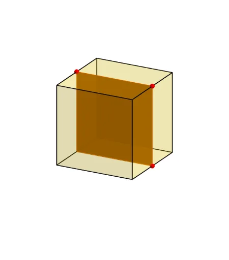
① This example dynamically demonstrates how different cutting planes intersect a cube, producing various cross-sections ranging from triangles to hexagons. ② Core mathematical concepts include solid geometry, plane-section intersections, and spatial relationships among points, lines, and planes. ③ Construction highlights: using GeoGebra commands such as Cube to build the cube, Polygon for faces, PointIn to place points on faces, Plane to define the cutting plane, IntersectPath to compute intersection segments with edges, OrthogonalLine for perpendiculars, and Translate/Rotate for dynamic adjustments; objects include the cube's 12 edges, 6 faces, and auxiliary points. ④ Suitable for middle/high school solid geometry lessons or introductory college geometry, aiding spatial visualization and exploration of section properties, including area variations and extremal problems.
GeoGebra Commands & Parameters
Cube((-1.5, -1.5, 0), (1.5, -1.5, 0), xOyPlane) → m, M, face4, face5, face6, edge1, edge2, edge3, edge4, edge5, edge6, edge7, N, edge8, edge9, edge10, edge11, edge12, Q, R, S, T, face1, face2, face3Polygon(B + (-2, -2), B + (2, -2), B + (2, 2), B + (-2, 2)) → poly3, e, f, g, iPointIn(poly3) → CTranslate((0, 0, 0), Vector[B, C]) → APolygon(A + (-4, -4), A + (4, -4), A + (4, 4), A + (-4, 4)) → poly1, a, b, c, dRotate(Rotate[Translate[poly1, Vector[A, A + (0, 0, h)]], (90° * s), A + (0, 0, h), yAxis], (90° * t), A, zAxis) → poly2Rotate(D, 120°, (0, 0, 0)) → EPolygon(D, E, 3, xOyPlane) → poly4, j, k, l, FPoint(list1) → GPoint(list2) → HPoint(list3) → IPlane(G, I, H) → nIntersectPath(n, m) → poly6, poly5, V, p, q, r, a_1, b_1, c_1, e_1, f_1, poly7, K, L_1, O, P, J, L, URotate(m, 0, zAxis) → m'Rotate(m, 0, zAxis) → m'_1OrthogonalLine(A, n) → d_1
AI Drawing Prompt Reference
Draw a cube and then cut it with a tilted plane to produce a hexagonal cross-section. First, create a cube, then draw a quadrilateral as the base for the cutting plane, and place a point inside this quadrilateral. Use this point to generate a new quadrilateral through translation and rotation. Finally, define a plane using this new quadrilateral and intersect it with the cube to show dynamic changes in the cross-section.
The prompt above was compiled from the original drawing commands and is for reference only.