
Robot Trajectory Demo
Loading the math board and drawing, please wait…
In collections
LEGO MINDSTORMS robotics
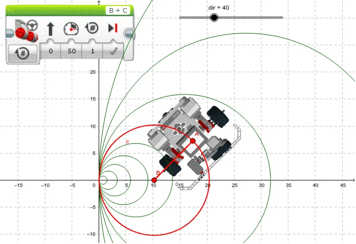
This example demonstrates how different circular trajectories are generated by changing the directional control of a robot. It involves core math concepts like vectors, rotation, locus, and coordinate geometry. Constructed using commands such as Circle, Point, Tangent, UnitVector, UnitOrthogonalVector, Sequence, and Segment. Suitable for high school mathematics education to understand parametric equations and geometric transformations in robot path planning.
GeoGebra Commands & Parameters
Circle((((100 - dir) / dir * L / 2), 0), ((100 - dir) / dir * L / 2)) → cPoint(c) → ATangent(A, c) → t, aUnitVector(t) → uUnitOrthogonalVector(t) → vSequence(Circle[(((100 - i) / i * L / 2), 0), ((100 - i) / i * L / 2)], i, 10, 90, 10) → list1Segment(B, A) → r
AI Drawing Prompt Reference
Draw a robot trajectory demonstration showing how different circular paths are generated by changing directional control. Include multiple circles with centers on the x-axis and radii that vary with angle. Start from the positive x-axis and draw 10 circles with 10-degree angular separation, with centers moving from far to near. Show a tangent line from the starting point to the first circle, and draw unit and orthogonal vectors based on the tangent direction. Finally, draw a line segment from the starting point to the center of the first circle.
The prompt above was compiled from the original drawing commands and is for reference only.