
Right and Oblique Cylinder
Loading the math board and drawing, please wait…
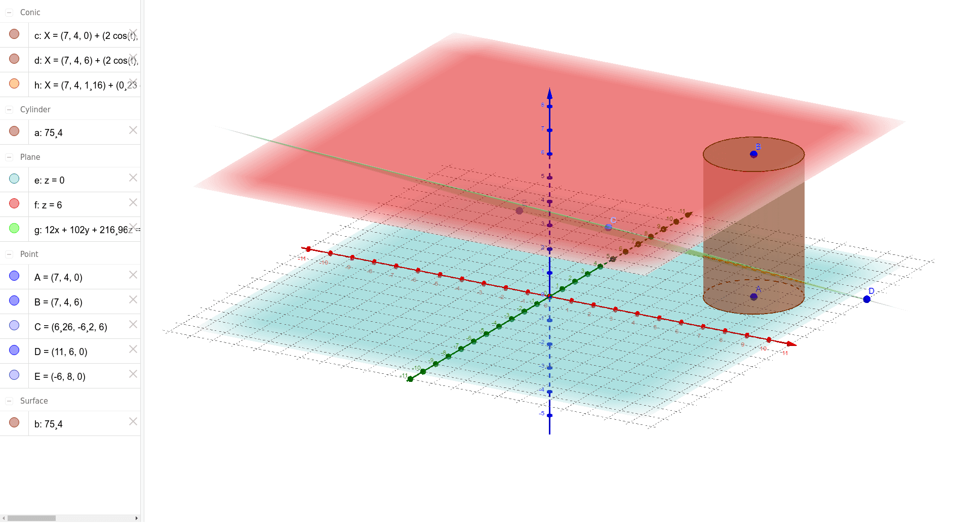
This example demonstrates the geometric construction and distinction between right and oblique cylinders. It involves core mathematical concepts such as cylinders, plane figures, geometric distribution, parallelograms, angles, and logic. The construction uses GeoGebra commands like Cylinder, Plane, PointIn, IntersectPath, and Corner with objects A, B, a, c, d, b, e, f, C, D, E, g, h. It is suitable for high school solid geometry education to understand the construction and properties of different types of cylinders.
GeoGebra Commands & Parameters
Cylinder(A, B, 2) → a, c, d, bPlane(c) → ePlane(B, e) → fPointIn(f) → CPointIn(e) → EPlane(C, D, E) → gIntersectPath(g, a) → hCorner(h)
AI Drawing Prompt Reference
Draw a right cylinder and an oblique cylinder to demonstrate their geometric construction and distinction. Start by creating a cylinder with a specified height of 2, using one point as the base center and another as the top center. Then, construct two planes based on the cylinder's lateral surface and top. Identify key points on these planes. Use these points to form a geometric structure involving parallelograms and angles, ultimately creating an oblique cylinder and highlighting the key points and intersection lines.
The prompt above was compiled from the original drawing commands and is for reference only.