
Quick Discovery of Perpendicular Lines: Intersection and Angle
Loading the math board and drawing, please wait…
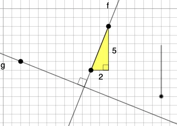
This GeoGebra example demonstrates how to construct a perpendicular (orthogonal) line to a given line from a chosen point, and then visualize the resulting intersection point, the angle between the lines, and related distance measures. Key concepts include perpendicular lines (orthogonality), slope/gradient constraints (via Slope), constructing an orthogonal line (OrthogonalLine), finding intersection points (Intersect), and interpreting direction relationships through the angle (Angle). The construction focuses on: creating initial lines with Line, computing or using slope information with Slope, generating the perpendicular line using OrthogonalLine, locating key intersection points with Intersect, and marking the angle with Angle. It further measures geometric relationships using Segment and Distance. The build uses GeoGebra commands such as Line, Slope, OrthogonalLine, Intersect, Angle, Polygon, Segment, Distance, along with Vector, Translate, Rotate, and Dilate to compare transformed configurations. Suitable for secondary school geometry, coordinate geometry introductions, and geometric construction practice.
GeoGebra Commands & Parameters
Line(A, B) → fSlope(f) → aDenominator(a) → runNumerator(a) → riseOrthogonalLine(C, f) → gIntersect(f, g) → DAngle(B, D, C) → αIntersect(h, i) → EPolygon(A, E, B) → t1, b, a_1, eSegment(A, E) → jSegment(E, B) → kSegment(B, A) → lDistance(C, F) → distanceCFDistance(B, E) → distanceBEIntersect(g, n) → GDilate(A, If[0 < c ≤ 1, 1 - c, 0], G) → A'Vector(A, A') → uTranslate(A, u) → A'_1Translate(E, u) → E'Translate(B, u) → B'Polygon(A'_1, E', B') → t1', b', a'_1, e'Segment(A'_1, E') → pSegment(E', B') → qSegment(B', A'_1) → rAngle(B', E', A'_1) → βAngle(B, E, A) → γRotate(A'_1, If[1 < c ≤ 2, ((c - 1) * π / 2), π / 2], G) → HRotate(E', If[1 < c ≤ 2, ((c - 1) * π / 2), π / 2], G) → E''Rotate(B', If[1 < c ≤ 2, ((c - 1) * π / 2), π / 2], G) → B''Polygon(H, E'', B'') → t1'', b'', h_1, e''Segment(G, E'') → sSegment(E'', B'') → tSegment(B'', G) → dAngle(B'', E'', G) → δ
AI Drawing Prompt Reference
Construct a coordinate-plane diagram with a given line determined by two points and a chosen reference point. From that point, draw the perpendicular (orthogonal) line to the given line and mark their intersection point. Display the angle formed by the given line and the perpendicular, and also show an additional angle defined by the corresponding three points. Add segments and distance measurements to illustrate key lengths from the intersection to the main points. Then translate the main triangle formed by the original points to a new position, drawing the translated triangle, its corresponding segments, and the same type of angle marking. Finally, rotate the translated part by a quarter-turn about the intersection point to form a rotated configuration and label its resulting angle.
The prompt above was compiled from the original drawing commands and is for reference only.