
Protractor Practice: Build an Angle, Then Measure It
Loading the math board and drawing, please wait…
In collections
Some terms & definitions. Angles, angle pairs, angle measure
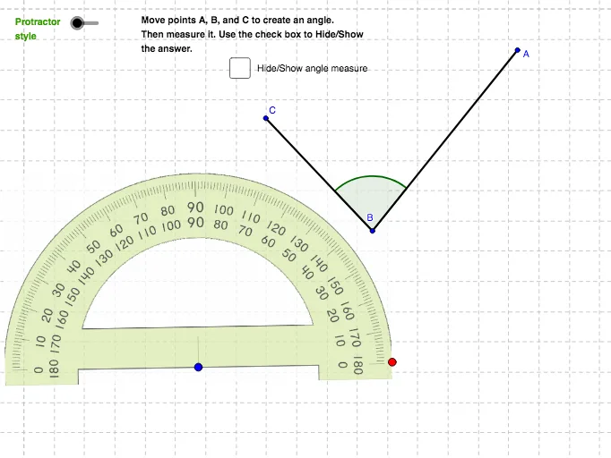
This example demonstrates an interactive workflow: students first construct an angle in the coordinate plane (by choosing rays/points and shaping the configuration), and then measure the constructed angle using a protractor tool to verify the result. The core concepts include the geometric definition of an angle, constructing angles via lines/segments and intersection points, and using angle-measuring tools (protractor-based measurement) to connect the visual construction with numerical angle values. Construction is carried out with GeoGebra commands such as Circle, Line, Intersect, Rotate, Angle, Segment, and Point; it also includes explicit protractor objects (e.g., protractor and protrac2) and angle/label displays. Typical objects include multiple points and angle notations (like α, β, γ, δ, ε, ζ, θ), along with auxiliary graphics (such as pic1/pic2 and measurement text). Suitable for middle and high school geometry lessons, classroom demonstrations, and student practice on angle measurement and geometric construction.
GeoGebra Commands & Parameters
Circle(B_1, a) → cLine(B_1, xAxis) → bIntersect(c, b, 2) → C_1Rotate(C_1, α, B_1) → C_2Angle(C_1, B_1, C_2) → βSegment(B_1, C_2) → dRotate(C_2, γ, B_1) → A_1Angle(C_2, B_1, A_1) → δSegment(B_1, A_1) → eCircle(D, f) → gPoint(g) → ERotate(E, (-ε), D) → E'Angle(E', D, E) → ζRotate(E, 184°, D) → E'_1Angle(E, D, E'_1) → ηCircle(F, protrac2) → hPoint(h) → GRotate(G, (-adjust), F) → G'Angle(G', F, G) → θRotate(G, adjust + 180°, F) → G'_1Angle(G, F, G'_1) → ιAngle(C, B, A) → κSegment(B, A) → iSegment(B, C) → j
AI Drawing Prompt Reference
Draw a figure on a coordinate plane that includes multiple points, rays, line segments, and circles. First, draw a circle and a line intersecting the x-axis to get a point. Then, rotate these points to form angles and connect them with line segments. Next, draw a circle and a point, and rotate and connect them to form another angle. Finally, draw some line segments and circles, and label the angles. The figure includes multiple points, rays, line segments, and circles, along with angle markers. The construction order starts from basic points and gradually adds elements and connects them.
The prompt above was compiled from the original drawing commands and is for reference only.