
Planar Graph 3: Intersections of Quadrilaterals and Polygons
Loading the math board and drawing, please wait…
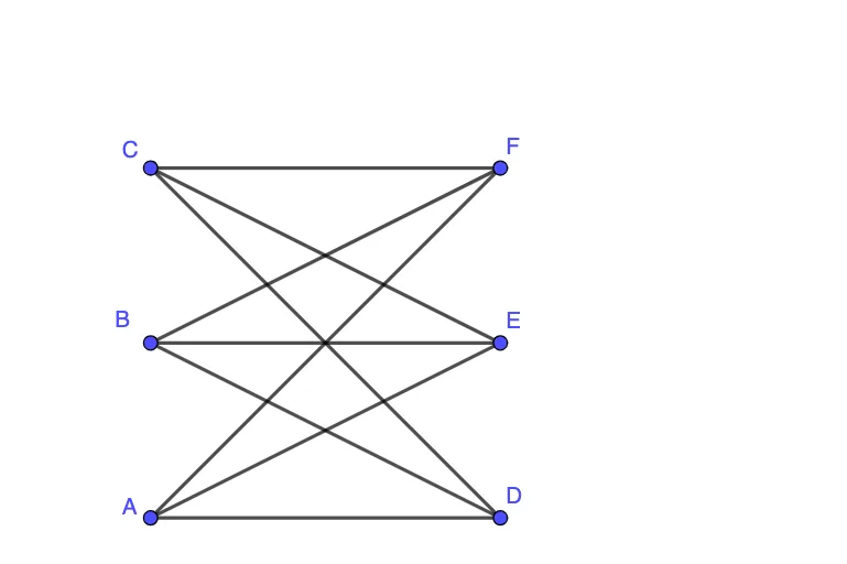
This GeoGebra example demonstrates the construction of a planar graph by connecting multiple points with segments and generating new points through intersections, resulting in a complex diagram of quadrilaterals, polygons, and crossing lines. The core mathematical concepts involve planar graph theory (vertices, edges, faces), properties of quadrilaterals and polygons, and an intuitive connection to continuity in calculus. The construction uses the Segment command to create lines such as AD, AE, AF, BD, BE, BF, CD, CE, CF, the Intersect command to find intersection points (G, H, I, etc.), and the If command to conditionally control object visibility or logic. This example is suitable for upper secondary or early university students to explore geometric construction, intersection computation, and conditional logic in dynamic geometry software, serving as a practical introduction to graph theory or advanced geometric drawing.
GeoGebra Commands & Parameters
Segment(A, D) → ADSegment(A, E) → AESegment(A, F) → AFSegment(B, D) → BDSegment(B, E) → BESegment(B, F) → BFSegment(C, D) → CDSegment(C, E) → CESegment(C, F) → CFIntersect(AD, BE) → GIntersect(AD, BF) → HIntersect(AD, CE) → IIntersect(AD, CF) → JIntersect(AE, BD) → KIntersect(AE, BF) → LIntersect(AE, CD) → MIntersect(AE, CF) → NIntersect(AF, BD) → OIntersect(AF, BE) → PIntersect(AF, CD) → QIntersect(AF, CE) → RIntersect(BD, CE) → SIntersect(BD, CF) → TIntersect(BE, CD) → UIntersect(BE, CF) → VIntersect(BF, CD) → WIntersect(BF, CE) → ZIf(Defined[G] ∨ Defined[H] ∨ Defined[I] ∨ Defined[J] ∨ Defined[K] ∨ Defined[L] ∨ Defined[M] ∨ Defined[N] ∨ Defined[O] ∨ Defined[P] ∨ Defined[Q] ∨ Defined[R] ∨ Defined[S] ∨ Defined[T] ∨ Defined[U] ∨ Defined[V] ∨ Defined[W] ∨ Defined[Z], 0, 1) → output
AI Drawing Prompt Reference
Draw a planar graph with multiple vertices and edges by connecting points A, B, C, D, E, and F with line segments such as AD, AE, AF. Then find the intersection points of these segments, such as the intersection of AD and BE, which is point G, and so on, to form complex polygons and crossing lines. Finally, control the visibility of objects based on whether the intersection points are defined.
The prompt above was compiled from the original drawing commands and is for reference only.