
Pinhole Camera Imaging Geometry Modeling
Loading the math board and drawing, please wait…
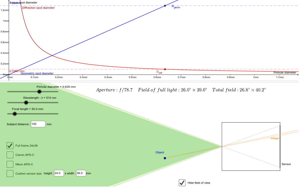
This GeoGebra applet demonstrates the geometric imaging principle of a pinhole camera, showing how light rays pass through a small aperture to form an inverted real image on a sensor surface. Core mathematical concepts include straight-line geometry, ray-segment intersections, orthogonal projection, similar-triangle proportions, and linear function modeling. The construction employs GeoGebra commands such as Ray, Segment, Intersect, Textfield, OrthogonalLine, Angle, and Line, together with objects including lambda, DistObject, CapteurY/X, f, diameter, TrouInf/Sup, C, D, F, G, capteur, RayonInf/Sup, ImInf/Sup, Image, and diffraction-related variables. Designed for screens of 10 inches or larger, it is suitable for high school physics and mathematics interdisciplinary teaching, as well as introductory university optics courses, supporting classroom demonstrations and student inquiry into aperture size, image formation, and diffraction effects.
GeoGebra Commands & Parameters
Ray(TrouSup, C) → DiaphSupRay(TrouInf, D) → DiaphInfSegment(F, G) → capteurRay(Object, TrouInf) → RayonInfRay(Object, TrouSup) → RayonSupIntersect(capteur, RayonInf) → ImInfIntersect(capteur, RayonSup) → ImSupSegment(ImInf, ImSup) → ImageTextfield(CapteurPersoY) → CapteurLargTextfield(CapteurPersoX) → CapteurLongSegment(H, I) → HIOrthogonalLine(H, DiaphSup) → aOrthogonalLine(I, DiaphInf) → bIntersect(a, DiaphSup) → AIntersect(b, DiaphInf) → BSegment(TrouInf, B) → cSegment(B, I) → dSegment(H, A) → eSegment(TrouSup, A) → gTextfield(DistObject) → ChampTexte1Ray(F, TrouInf) → ChampTotalInfRay(G, TrouSup) → ChampTotalSupRay(F, TrouSup) → ChampPLInfRay(G, TrouInf) → ChampPLSupAngle(ChampPLSup, ChampPLInf) → AngleChampPLLAngle(ChampTotalSup, ChampTotalInf) → AngleChampTotalLLine(D_{diff}, xAxis) → DroiteTacheDiffLine(D_{geom}, xAxis) → DroiteTacheGeom
AI Drawing Prompt Reference
Draw a pinhole camera imaging geometry model showing how light rays pass through a small aperture to form an inverted real image. Include two light rays emitted from a source, passing through the aperture and intersecting the sensor surface at two points, forming an image line connecting these points. The sensor surface is a horizontal line segment with labeled length and width. Draw perpendicular lines from the aperture to the light rays, connecting the intersection points with the aperture to form two auxiliary line segments. Finally, add two parallel lines near the sensor surface to represent diffraction and geometric imaging effects.
The prompt above was compiled from the original drawing commands and is for reference only.