
Orientation Visualization in 3D: Rotation, Helix, and Geometric Transformations
Loading the math board and drawing, please wait…
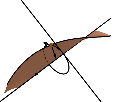
This GeoGebra example provides an interactive 3D visualization of spatial orientation, demonstrating how direction vectors, orthogonal planes, cylinders, and helical curves can be combined to illustrate orientation and rotation in space. The core mathematical concepts include 3D vectors, orthogonal planes, rotation, translation, parametric equations of helices, and coordinate transformations. The construction uses a rich set of GeoGebra commands: Line, OrthogonalPlane, PointIn, Plane, Intersect, Segment, Point, Vector, Cylinder, CurveCartesian, Rotate, Surface, Translate, and Circle. It defines numerous objects such as points (A, B, C, D, E, F, G, H, I), lines (a, b, c, d, e, f, g, h), planes, vectors (u, v, w, t), and helical curves (helix, helix1), with a slider (thickness) to adjust parameters. This example is suitable for high school and university students learning solid geometry, vector analysis, and spatial transformations, as well as for instructors in linear algebra or computer graphics who need a visual aid for orientation and rotation concepts.
GeoGebra Commands & Parameters
Line(A, B) → fOrthogonalPlane(B, f) → aPointIn(a) → CPointIn(a) → DLine(C, D) → gOrthogonalPlane(D, g) → bPlane(B, b) → cIntersect(g, c) → ESegment(B, E) → hPoint(f) → FVector(B, F) → uVector(B, E) → vVector(E, E + u ⊗ v) → wCylinder(H, I, thickness) → d, e, k, iCurveCartesian(E + ((u * sin(t)) * Length[v] / Length[u]) - (v * cos(t)) + (t * w), t, (-2 * π), (2 * π)) → helixRotate(B, (-t), g) → GSurface((s * helix(t)) + ((1 - s) * (E + (t * w))), t, (-2 * π), (2 * π), s, 0, 1) → nTranslate(i, Vector[(π * w)]) → i'Translate(i', Vector[(π * w)]) → i''Translate(i'', Vector[(π * w)]) → i'''Translate(i''', Vector[(2 * w)]) → oVector(G, G + Rotate[v, (-t), g]) → jVector(G, G + Rotate[u, (-t), g]) → lRotate(helix, (-t), g) → helix1Rotate(n, (-t), g) → n'Circle(E, Length[v], w) → p
AI Drawing Prompt Reference
Draw a 3D visualization of direction vectors and rotations. Start by creating points A and B, then create line f through A and B. Create plane a perpendicular to f through B, and on a create points C and D, then create line g through C and D. Create plane b perpendicular to g through D, and on b create point E, then connect BE. Create vectors u and v, and vector w. Use points H and I to create cylinder d, e, k, i. Then draw helix, rotate point B to get point G, create surface n, translate cylinder i three times to get i', i'', i'''. Create two rotation vectors j and l for point G, rotate helix to get helix1, rotate surface n to get n', and finally create circle p.
The prompt above was compiled from the original drawing commands and is for reference only.