
One Fixed End Linkage
Loading the math board and drawing, please wait…
In collections
Linkages
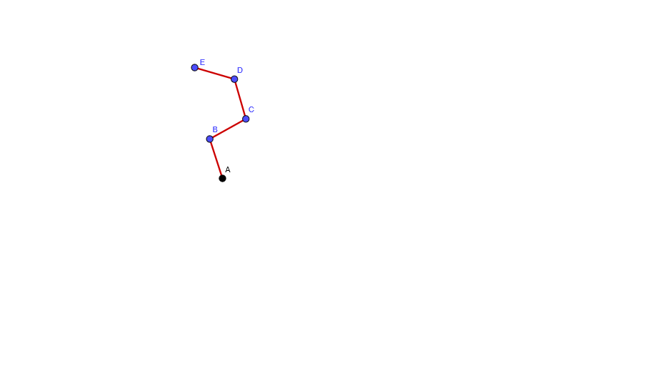
This example demonstrates the motion of a linkage mechanism. Key mathematical concepts include geometric transformations and loci. Using GeoGebra commands for objects A, B, C, D, E, and barras, a linkage mechanism is constructed. Suitable for high school geometry or mechanical engineering studies.
GeoGebra Commands & Parameters
Point A(0.17257096113912795, 2.89425849113616)Point B(-0.1357370991090936, 3.8455450620420977)Point C(0.7383113423063093, 4.331383844005112)Point D(0.4610244005542703, 5.292170996257783)Point E(-0.4991863711146674, 5.571447336055741){Segment[A, B], Segment[B, C], Segment[C, D], Segment[D, E]}
AI Drawing Prompt Reference
Draw a linkage mechanism with five points A, B, C, D, and E, connecting them with line segments AB, BC, CD, and DE, and observe the motion of these points and segments.
The prompt above was compiled from the original drawing commands and is for reference only.