
Oblique Cylinder Construction in 3D Geometry
Loading the math board and drawing, please wait…
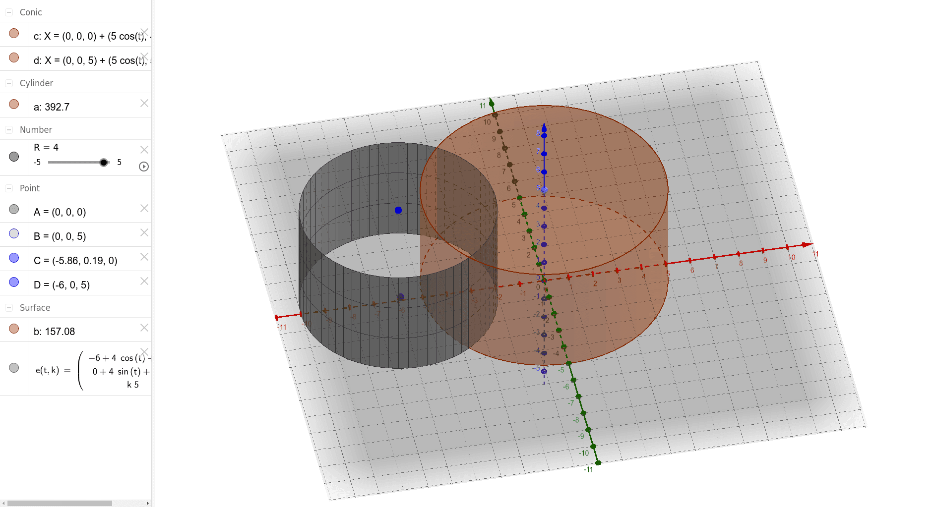
① This example demonstrates how to construct an oblique cylinder in GeoGebra, where the lateral surface is not perpendicular to the base, showing its 3D spatial form. ② Core mathematical concepts include solid geometry definitions of cylinders, generation of oblique cylinders by translating a base circle along a non-perpendicular direction, and intersection relationships among points, lines, and surfaces in space. ③ Construction highlights: from the construction summary, commands such as Intersect, Point, Cylinder, and Surface are used, with objects A, B, a, c, d, b, R, C, D, e defined; R likely denotes radius, while C and D are key points used to define the cylinder via intersections or surface generation. ④ Suitable for high school or early college students learning solid geometry and spatial visualization, as well as for math teachers creating 3D geometry demonstrations to help students intuitively distinguish oblique cylinders from right cylinders.
GeoGebra Commands & Parameters
Intersect(zAxis, xAxis) → APoint(zAxis) → BCylinder(A, B, 5) → a, c, d, bSurface(x(D) + (R * cos(t)) + (k * (x(B) - x(A))), y(D) + (R * sin(t)) + (k * (y(B) - y(D))), (k * z(B)), t, 0, (2 * π), k, 0, 1) → e
AI Drawing Prompt Reference
Draw an oblique cylinder in 3D space. Start by placing a base circle with radius 5 centered at the origin, where the coordinate axes intersect. Choose a point on the vertical axis as the center of the top circle. The top circle has the same radius but is shifted horizontally relative to the base, creating a slanted side. Connect corresponding points on the two circles with straight lines to form the lateral surface, which is a curved surface. The cylinder appears tilted, with its axis not perpendicular to the base, illustrating the concept of an oblique cylinder in solid geometry.
The prompt above was compiled from the original drawing commands and is for reference only.