
Moment Diagram for Cantilever Beam
Loading the math board and drawing, please wait…
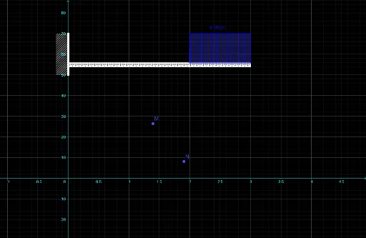
This example demonstrates the method of drawing the moment diagram for a cantilever beam using the area-moment method. Key mathematical concepts include area-moment and moment. Using GeoGebra commands such as Point, Segment, Polygon, and Intersect, the essential parts of the moment diagram are constructed. Suitable for university-level engineering mechanics courses.
GeoGebra Commands & Parameters
Point(yAxis) → APoint(yAxis) → BSegment(A, B) → fPolygon(A, B, C, D) → q1, a, b, c, dPoint(f) → EPoint(f) → HPolygon(E, F, G, H) → q2, e, f_1, g, hPoint(g) → IIntersect(f_1, g) → LPolygon(I, J, K, L) → q3, i, j, k, l
AI Drawing Prompt Reference
Draw a moment diagram for a cantilever beam, featuring a horizontal baseline with three successively larger trapezoidal regions above it, each representing different bending moments, formed by connecting points on the baseline to intersections with curves, showing an increasing moment profile from left to right.
The prompt above was compiled from the original drawing commands and is for reference only.