
Area-Moment Method: Moment Diagram by Parts (Cantilever Beam)
Loading the math board and drawing, please wait…
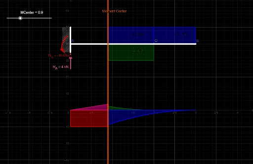
① This example demonstrates the Area-Moment Method applied to a cantilever beam, breaking the moment diagram into parts and visually showing the area and centroid of each part to compute beam rotations and deflections. ② Core mathematical concepts include moment diagrams, area-moment, centroid, integration, and geometric decomposition, rooted in classical structural mechanics. ③ Construction highlights: from the summary, GeoGebra commands such as Segment, Polygon, IntegralBetween, Vector, Intersect, and Point are used to create the beam axis, load distribution function, partitioned moment polygons, integral regions, vector arrows, and key intersection points, with auxiliary points (e.g., MCenter, E, F) marking centroids and characteristic locations. ④ This is suitable for university-level courses in Mechanics of Materials or Structural Mechanics, serving as a teaching aid for explaining the area-moment method, and also for engineering students self-studying moment diagram decomposition and centroid calculation.
GeoGebra Commands & Parameters
Segment(A, B) → fSegment(C, D) → gPolygon(H, A, B, G) → q1, h, a, b, g_1IntegralBetween(50, 40, 2, 3) → cVector(E, B) → uIntegralBetween(p, 40, MCenter, 2) → dIntegralBetween(40, r, MCenter, 2) → eIntersect(t, q) → IIntersect(xAxis, q) → JIntersect(t, xAxis) → KPolygon(K, J, I) → t1, i, k, jIntegralBetween(0, -10, 0, MCenter) → lIntegralBetween(-10, s, 2, MCenter) → mIntegralBetween(f_1, 0, MCenter, 2) → nIntegralBetween(0, h_1, MCenter, 3) → oPoint(f) → LVector(M, N) → wSegment(Q, P) → i_1Segment(O, M) → j_1Segment(P, O) → k_1
AI Drawing Prompt Reference
Draw a cantilever beam's moment diagram using the area-moment method. Start by drawing the beam axis, then add the load distribution function. Divide the moment diagram into several parts and use polygons to represent the area and centroid of each part. Calculate the area and centroid of each part, and use vectors to indicate the load direction. Mark key intersection points and centroids, and finally use polygons to represent the different parts of the moment diagram.
The prompt above was compiled from the original drawing commands and is for reference only.