
Modeling the Cube
Loading the math board and drawing, please wait…
In collections
Linkages
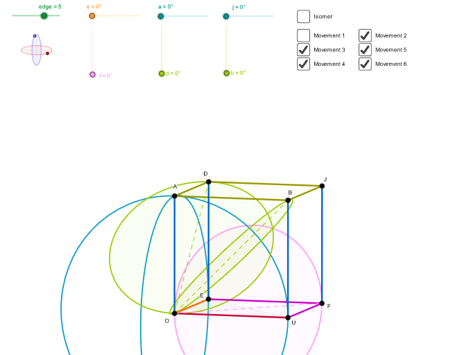
This example demonstrates the geometric construction of a cube. Key mathematical concepts include geometric transformations, reflections, and parametric curves. Using GeoGebra commands such as If, OrthogonalLine, and Circle, the cube's faces and edges can be dynamically constructed. Suitable for middle school and above students or teachers for geometry instruction.
GeoGebra Commands & Parameters
If(f ≟ 0° ∨ f ≟ 90° ∨ f ≟ 180° ∨ f ≟ 270° ∨ f ≟ 360°, f + 0.001, f) → f'If(b ≟ 0° ∨ b ≟ 90° ∨ b ≟ 180° ∨ b ≟ 270° ∨ b ≟ 360°, b + 0.001, b) → b'If(a ≟ 0° ∨ a ≟ 90° ∨ a ≟ 180° ∨ a ≟ 270° ∨ a ≟ 360°, a + 0.001, a) → a'If(j ≟ 0° ∨ j ≟ 90° ∨ j ≟ 180° ∨ j ≟ 270° ∨ j ≟ 360°, j + 0.001, j) → j'If(a ≟ 90°, 2, If[a ≟ 270°, 0, Ny + (cos(b) * Ny) + ((sin(b) * NPy) * sqrt(Nx^(2) + Ny^(2) + Nz^(2)) / sqrt(NPx^(2) + nada^(2) + NPz^(2)))]) → ByIf(a ≟ 90° ∨ a ≟ 270°, 0, Nz + (cos(b) * Nz) + ((sin(b) * NPz) * sqrt(Nx^(2) + Ny^(2) + Nz^(2)) / sqrt(NPx^(2) + nada^(2) + NPz^(2)))) → BzIf(e ≟ 0° ∨ e ≟ 90° ∨ e ≟ 180° ∨ e ≟ 270° ∨ e ≟ 360°, e + 0.001, e) → e'If((((((sgn(cos(e)) * sgn(cos(a))) * sgn(cos(j))) * sgn(cos(f))) * sgn(cos(d))) * sgn(cos(b))) ≟ 0, (((((sgn(cos(e + 0.01°)) * sgn(cos(a + 0.01°))) * sgn(cos(j + 0.01°))) * sgn(cos(f + 0.01°))) * sgn(cos(d + 0.01°))) * sgn(cos(b + 0.01°))), (((((sgn(cos(e)) * sgn(cos(a))) * sgn(cos(j))) * sgn(cos(f))) * sgn(cos(d))) * sgn(cos(b)))) → signoIf(d ≟ 0° ∨ d ≟ 90° ∨ d ≟ 180° ∨ d ≟ 270° ∨ d ≟ 360°, d + 0.001, d) → d'OrthogonalLine(C, xAxis) → zz2Circle(C, 0.62) → zz0Intersect(zz0, zz2, 1) → ZZ4Intersect(zz0, zz2, 2) → ZZ3Ellipse(ZZ3, ZZ4, 0.65) → zElipse2Point(zElipse2) → ZOrthogonalLine(C, yAxis) → zz1Intersect(zz0, zz1, 2) → ZZ2Intersect(zz0, zz1, 1) → ZZ1Ellipse(ZZ1, ZZ2, 0.65) → zElipse1Point(zElipse1) → XYPunto3D(C, XY, Z, LJ1) → J1Punto3D(C, XY, Z, LJ2) → J2Punto3D(C, XY, Z, LE) → EIntersect(zElipse2, zz2) → ZZ7, ZZ8Angle(ZZ8, C, Z) → zAngIncIntersect(zElipse1, zz1) → ZZ5, ZZ6Angle(ZZ6, C, XY) → zAngRotSegment(ZZ5, ZZ6) → zz4Segment(ZZ7, ZZ8) → zz3Intersect(zElipse2, zElipse1, 1) → zPunto1Intersect(zElipse2, zElipse1, 4) → zPunto2Segment(zPunto1, zPunto2) → zSeg2Point(Circle[AuxX, distancia3D]) → AuxYSegment(AuxX, AuxY) → segmentodistancia3DPunto3D(C, XY, Z, LU) → UPunto3D(C, XY, Z, LO) → OPunto3D(C, XY, Z, LF) → FPunto3D(C, XY, Z, LA) → APolygon(O, E, U) → poly1, poly1c, poly1b, poly1aPunto3D(C, XY, Z, LB) → BSegment(O, U) → barraOUSegment(O, E) → barraOESegment(U, F) → barraUFSegment(F, E) → barraEFSegment(O, A) → barraOASegment(A, B) → barraABIf(isomero, J1, J2) → JSegment(B, J) → barraBJSegment(U, B) → barraUBSegment(F, J) → barraFJPunto3D(C, XY, Z, LD) → DSegment(A, D) → barraADSegment(E, D) → barraEDSegment(D, J) → barraDJPunto3D(C, XY, Z, LM) → MPunto3D(C, XY, Z, LMP) → MPPunto3D(C, XY, Z, LNP) → NPIf((((((sgn(cos(e)) * sgn(cos(a))) * sgn(cos(j))) * sgn(cos(f))) * sgn(cos(d))) * sgn(cos(b))) ≟ 0, (((((sgn(cos(e - 0.01°)) * sgn(cos(a - 0.01°))) * sgn(cos(j - 0.01°))) * sgn(cos(f - 0.01°))) * sgn(cos(d - 0.01°))) * sgn(cos(b - 0.01°))), (((((sgn(cos(e)) * sgn(cos(a))) * sgn(cos(j))) * sgn(cos(f))) * sgn(cos(d))) * sgn(cos(b)))) → cSequence({((-cos(e)) * arista), (sin(e) * arista), 0}, e, 8°, 300.00000000000006°, 72°) → LCE, {{-4.951340343707852, 0.6958655048003272, 0}, {-0.8682408883346521, 4.92403876506104, 0}, {4.414737964294635, 2.3473578139294533, 0}, {3.5966990016932554, -3.4732918522949867, 0}, {-2.191855733945387, -4.493970231495835, 0}}Conic(Punto3D[C, XY, Z, Element[LCE, 1]], Punto3D[C, XY, Z, Element[LCE, 2]], Punto3D[C, XY, Z, Element[LCE, 3]], Punto3D[C, XY, Z, Element[LCE, 4]], Punto3D[C, XY, Z, Element[LCE, 5]]) → CESequence({(arista * (Ex / 2 - (((sgn(cos(e)) * dF) * cos(f)) * sin(aF)))), (arista * ((Ey + 1) / 2 + ((dF * cos(f)) * cos(aF)))), ((arista * dF) * sin(f))}, f, 8°, 300.00000000000006°, 72°) → LCFF, {{-4.975667684019047, 4.980645841196502, 0.49229718133007855}, {-2.934118977107226, 2.937054564122473, 3.483561676900716}, {-0.2926308715371856, 0.29292364882176347, 1.660662336901143}, {-0.7016501483281518, 0.7023521495355842, -2.4572159088589807}, {-3.59592606900891, 3.599523794240345, -3.179305286272957}}Conic(Punto3D[C, XY, Z, Element[LCFF, 1]], Punto3D[C, XY, Z, Element[LCFF, 2]], Punto3D[C, XY, Z, Element[LCFF, 3]], Punto3D[C, XY, Z, Element[LCFF, 4]], Punto3D[C, XY, Z, Element[LCFF, 5]]) → CFFSequence({((arista * sin(j)) * cos(a)), (arista * sin(a)), ((arista * cos(j)) * cos(a))}, a, 8°, 300.00000000000006°, 72°) → LCA, {{0, 0.6958655048003272, 4.951340343707852}, {0, 4.92403876506104, 0.8682408883346521}, {0, 2.3473578139294533, -4.414737964294635}, {0, -3.4732918522949867, -3.5966990016932554}, {0, -4.493970231495835, 2.191855733945387}}Conic(Punto3D[C, XY, Z, Element[LCA, 1]], Punto3D[C, XY, Z, Element[LCA, 2]], Punto3D[C, XY, Z, Element[LCA, 3]], Punto3D[C, XY, Z, Element[LCA, 4]], Punto3D[C, XY, Z, Element[LCA, 5]]) → CASequence({((arista * sin(j)) * cos(a)), (arista * sin(a)), ((arista * cos(j)) * cos(a))}, j, 8°, 300.00000000000006°, 72°) → LCJ, {{0.6958655048003272, 0, 4.951340343707852}, {4.92403876506104, 0, 0.8682408883346521}, {2.3473578139294533, 0, -4.414737964294635}, {-3.4732918522949867, 0, -3.5966990016932554}, {-4.493970231495835, 0, 2.191855733945387}}Conic(Punto3D[C, XY, Z, Element[LCJ, 1]], Punto3D[C, XY, Z, Element[LCJ, 2]], Punto3D[C, XY, Z, Element[LCJ, 3]], Punto3D[C, XY, Z, Element[LCJ, 4]], Punto3D[C, XY, Z, Element[LCJ, 5]]) → CJSequence({(arista * ((((((sqrt(2) * cos(a)) * sin(d)) * sin(e)) * cos(j)) * sqrt((((-cos(a)) * cos(e)) * sin(j)) + (sin(a) * sin(e)) + 1) / ((2 * sqrt(((cos(a))^(2) * (((sin(e))^(2) * (sin(j))^(2)) + (cos(j))^(2))) + (((((2 * sin(a)) * cos(a)) * sin(e)) * cos(e)) * sin(j)) + ((sin(a))^(2) * (cos(e))^(2)))))) + (cos(a) * ((cos(d) * sin(j) / 2) + sin(j) / 2)) - (cos(d) * cos(e) / 2) - cos(e) / 2)), (arista * ((((((sqrt(2) * cos(a)) * sin(d)) * cos(e)) * cos(j)) * sqrt((((-cos(a)) * cos(e)) * sin(j)) + (sin(a) * sin(e)) + 1) / ((2 * sqrt(((cos(a))^(2) * (((sin(e))^(2) * (sin(j))^(2)) + (cos(j))^(2))) + (((((2 * sin(a)) * cos(a)) * sin(e)) * cos(e)) * sin(j)) + ((sin(a))^(2) * (cos(e))^(2)))))) + (sin(a) * (cos(d) / 2 + 1 / 2)) + (cos(d) * sin(e) / 2) + sin(e) / 2)), (arista * ((cos(a) * ((cos(d) * cos(j) / 2) + cos(j) / 2)) - (((sqrt(2) * sin(d)) * (((cos(a) * sin(e)) * sin(j)) + (sin(a) * cos(e)))) * sqrt((((-cos(a)) * cos(e)) * sin(j)) + (sin(a) * sin(e)) + 1) / ((2 * sqrt(((cos(a))^(2) * (((sin(e))^(2) * (sin(j))^(2)) + (cos(j))^(2))) + (((((2 * sin(a)) * cos(a)) * sin(e)) * cos(e)) * sin(j)) + ((sin(a))^(2) * (cos(e))^(2))))))))}, d, 8°, 300.00000000000006°, 72°) → LCD, {{-4.975670171853926, 0.4920512172381114, 4.975670171853926}, {-2.934120444167326, 3.481821201600095, 2.934120444167326}, {-0.29263101785268253, 1.6598326281007467, 0.29263101785268253}, {-0.7016504991533723, -2.4559882217977695, 0.7016504991533723}, {-3.5959278669726933, -3.177716825141184, 3.5959278669726933}}Conic(Punto3D[C, XY, Z, Element[LCD, 1]], Punto3D[C, XY, Z, Element[LCD, 2]], Punto3D[C, XY, Z, Element[LCD, 3]], Punto3D[C, XY, Z, Element[LCD, 4]], Punto3D[C, XY, Z, Element[LCD, 5]]) → CDSequence({(arista * (((((sqrt(2) * sin(b)) * cos(j)) * sgn(cos(a))) * sqrt(sin(a) + 1) / 2) + (cos(a) * ((cos(b) * sin(j) / 2) + sin(j) / 2)))), (arista * ((sin(a) * (cos(b) / 2 + 1 / 2)) + cos(b) / 2 + 1 / 2)), (arista * ((cos(a) * ((cos(b) * cos(j) / 2) + cos(j) / 2)) - ((((sqrt(2) * sin(b)) * sin(j)) * sgn(cos(a))) * sqrt(sin(a) + 1) / 2)))}, b, 8°, 300.00000000000006°, 72°) → LCB, {{0.4920512172381114, 4.975670171853926, 4.975670171853926}, {3.481821201600095, 2.934120444167326, 2.934120444167326}, {1.6598326281007467, 0.29263101785268253, 0.29263101785268253}, {-2.4559882217977695, 0.7016504991533723, 0.7016504991533723}, {-3.177716825141184, 3.5959278669726933, 3.5959278669726933}}Conic(Punto3D[C, XY, Z, Element[LCB, 1]], Punto3D[C, XY, Z, Element[LCB, 2]], Punto3D[C, XY, Z, Element[LCB, 3]], Punto3D[C, XY, Z, Element[LCB, 4]], Punto3D[C, XY, Z, Element[LCB, 5]]) → CBSegment(O, F) → gSegment(O, D) → hSegment(O, B) → i
AI Drawing Prompt Reference
Draw a 3D cube construction diagram. First, set up a reference circle together with two perpendicular direction lines, then use their intersections to define key points that generate two ellipse-related loci. From these, pick the corresponding 3D points by using a shared base (same XY projection) with a chosen height to obtain the cube’s top and bottom vertices. Next, connect the appropriate vertex points with straight segments to form the visible cube edges, and trace polygonal faces by linking vertices in sequence. Include the main connecting segment(s) between a selected vertex pair to emphasize the cube’s spatial correspondence, producing a clear perspective view of the cube.
The prompt above was compiled from the original drawing commands and is for reference only.