
ME 201 Vector Addition Visualizer
Loading the math board and drawing, please wait…
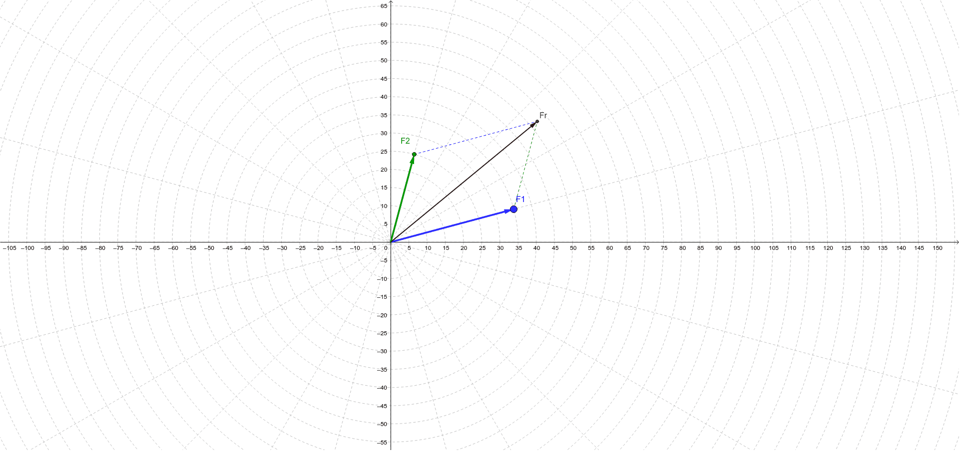
① This example demonstrates the addition of two force vectors (F1 and F2) using the parallelogram law, visually constructing the resultant vector Fr. ② Core mathematical concepts include vector addition, parallelogram rule, force composition, angles, and segment relationships, bridging linear algebra and geometry. ③ Construction highlights: uses GeoGebra commands such as Vector, Line, Intersect, Segment, and Angle; objects include F1, F2, a, b, c, m, n, Fr, p, q, E, F, and α; interactive sliders or instructions (instruct/instruct2) allow dynamic adjustment of vector magnitudes and directions. ④ Suitable for high school or early college physics/engineering courses (e.g., ME 201) to study vector operations and force resolution, and for mathematics classes to illustrate the geometric meaning of vector addition, clarifying the equivalence of parallelogram and triangle laws.
GeoGebra Commands & Parameters
Vector(F1) → aVector(F2) → bLine(F2, a) → mLine(F1, b) → nIntersect(m, n) → FrSegment(F1, Fr) → pSegment(F2, Fr) → qAngle(Fr, E, F) → α
AI Drawing Prompt Reference
Draw the parallelogram rule for adding two force vectors F1 and F2. First, draw F1 and F2, then construct lines m and n through F2 and F1 respectively. The intersection of m and n is the resultant vector Fr. Next, draw line segments p and q from F1 and F2 to Fr, and finally, mark the angle α between Fr and the horizontal line.
The prompt above was compiled from the original drawing commands and is for reference only.