
Magnetic Flux Density Component Perpendicular to the Wire
Loading the math board and drawing, please wait…
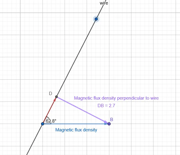
This GeoGebra example visualizes the component of magnetic flux density that is perpendicular to a current-carrying conductor using a two-dimensional geometric diagram. It demonstrates how a magnetic field vector can be decomposed into components relative to the wire's direction, emphasizing the perpendicular component which is crucial in electromagnetic force calculations (F = BIL sinθ). The core mathematical concepts include vector decomposition, right triangles, trigonometric functions (sine/cosine), and angle measurement. The construction uses GeoGebra commands such as Point, Vector, Line, OrthogonalLine, Angle, Intersect, Distance, and text labels to display the computed distance. It is suitable for high school physics or introductory university electromagnetism courses, as well as mathematics classes focusing on vector applications and trigonometry. The interactive nature allows students to manipulate the angle and observe how the perpendicular component changes, reinforcing the relationship between geometry and physics.
GeoGebra Commands & Parameters
Point(yAxis) → AVector(A, B) → uLine(A, C) → fOrthogonalLine(B, f) → gAngle(B, A, C) → αIntersect(f, g) → DVector(A, D) → vVector(D, B) → wDistance(D, B) → distanceDB
AI Drawing Prompt Reference
Create a 2D geometry diagram for a physics vector decomposition: include a reference line representing the wire direction, and define a magnetic field vector with a clear start point and end point. At the vector’s start, mark the angle between the vector and the reference line. Construct the perpendicular from the vector’s end point to the reference line, and obtain the intersection (the foot of the perpendicular). Draw vectors from the start point to that intersection and from the intersection to the original end point to represent the components related to the perpendicular direction. Display the distance between the intersection point and the original end point, and add text labels for the marked angle and the computed distance to highlight the perpendicular-component relationship.
The prompt above was compiled from the original drawing commands and is for reference only.