
Line Symmetry Linkage (Imai's Butterfly)
Loading the math board and drawing, please wait…
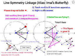
This example demonstrates the geometric construction and motion characteristics of the Line Symmetry Linkage, also known as Imai's Butterfly. It involves core mathematical concepts such as symmetry, geometric transformations, vector operations, function graphs, and three-dimensional vectors. The construction utilizes GeoGebra commands and objects like Circle, Intersect, Point, Segment, Mirror, Angle, Polygon, Dilate, and Midpoint. It is suitable for high school and above learners to understand the relationship between geometric transformations, vectors, and function graphs, as well as to explore the symmetry of complex mechanical structures.
GeoGebra Commands & Parameters
Circle(A, 2) → cIntersect(c, xAxis, 2) → A'Circle(A'_1, sqrt(2)) → q_1Point(c) → BCircle(A_1, 2) → sSegment(A_1, B_1) → iCircle(A_1, sqrt(2)) → qIntersect(q, i, 1) → FCircle(F, 2) → p_1Intersect(p_1, q_1, 2) → EMirror(A'_1, E) → DCircle(D, 2) → r_1Circle(A_1, (2 * sqrt(2))) → s_1Intersect(r_1, s_1, 2) → CSegment(A_1, C) → l_1Segment(A, B) → fMirror(B, xAxis) → B'Segment(A, B') → gAngle(A', A, B) → αAngle(B', A, A') → βSegment(A, A') → hSegment(A_1, A'_1) → jCircle(A'_1, (2 * sqrt(2))) → dCircle(A_1, (2 * sqrt(2))) → eSegment(A_1, C) → kCircle(C, 2) → pSegment(C, D) → lSegment(D, A'_1) → mSegment(A_1, A'_1) → nSegment(E, F) → rPolygon(A_1, F, E, A'_1) → poly1, a_1, f_1, e_1, a'_1Polygon(A_1, A'_1, D, C) → poly2, a_2, a'_2, d_1, c_1Intersect(s, l_1) → B'_1,Segment(B'_1, C) → tSegment(A_1, B'_1) → aDilate(G, 1.5, H) → G'Dilate(G, 1.5, I) → G'_1Segment(G', H) → bSegment(I, G'_1) → g_1Circle(G'_1, G) → h_1Circle(G', G) → k_1Intersect(h_1, k_1, 2) → JSegment(J, G'_1) → i_1Segment(J, G') → j_1Segment(G, K) → m_1Midpoint(L, N) → OSegment(O, P) → t_1Segment(P, M) → b_1Segment(L, M) → f_2Segment(Q, O) → g_2Segment(Q, S) → h_2Segment(R, S) → i_2Segment(R, P) → j_2Segment(U, T) → k_2Segment(O, N) → n_1Segment(L, O) → l_2Circle(V, (0.5 * 2)) → c_2Segment(V, W) → m_2Point(c_2) → ZCircle(Z, (0.5 * 3)) → d_2Segment(V, Z) → n_2Intersect(d_2, m_2, 1) → C_1Segment(Z, C_1) → p_2Circle(C_1, (0.5 * 2)) → e_2Circle(V, (0.5 * 3)) → q_2Intersect(e_2, q_2, 2) → D_1Segment(V, D_1) → r_2Segment(D_1, C_1) → s_2Circle(V, (0.5 * 4 / 3)) → t_2Intersect(t_2, r_2, 1) → E_1Circle(Z, (0.5 * 4 / 3)) → c_3Circle(E_1, 1) → d_3Intersect(c_3, d_3, 2) → F_1Segment(Z, F_1) → b_2Segment(F_1, E_1) → f_3Polygon(F_1, Z, V, E_1) → poly3, f_4, z_1, v, e_3Angle(F_1, Z, V) → γAngle(V, Z, C_1) → δ