
Law of Reflection of Light Visualization
Loading the math board and drawing, please wait…
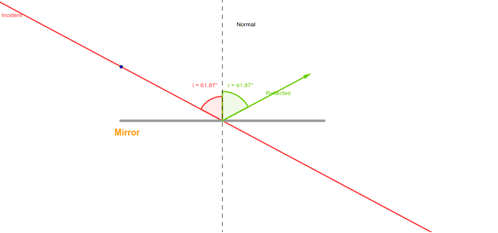
This GeoGebra example demonstrates the law of reflection of light, dynamically showing the geometric relationship between incident ray, reflected ray, and normal. Core mathematical concepts include: angle of incidence equals angle of angle of reflection, angle measurement, and angle bisector properties. Construction details: Use Point command to create points A and B, LineBisector to construct normal line, Angle command to measure incident and reflected angles, Rotate to transform light ray around the normal, and Vector to represent ray direction vectors. Suitable for secondary school physics optics teaching and geometry angle concept instruction, useful for demonstrating the dynamic derivation of reflection law.
GeoGebra Commands & Parameters
Point(xAxis) → APoint(xAxis) → BSegment(A, B) → aLineBisector(a) → NormalIntersect(Normal, a) → CPoint(Normal) → EAngle(E, C, D) → iRotate(E, (-i), C) → E'Angle(E', C, E) → rVector(C, E') → ReflectedLine(D, C) → Incident
AI Drawing Prompt Reference
Draw a horizontal segment as the reflecting surface with two endpoints. Construct the perpendicular bisector of this segment as the normal line, intersecting the segment at its midpoint. Place a point on the normal above the midpoint, and draw a ray from this point to the midpoint as the incident ray. Measure the angle between the incident ray and the normal, then rotate the incident ray around the midpoint by this angle to the other side of the normal, creating the reflected ray. Finally, add arrows from the midpoint along both rays to indicate direction, and label the incident and reflected angles to show they are equal.
The prompt above was compiled from the original drawing commands and is for reference only.