
Geometric Bounds for a Definite Integral Using Isosceles Triangles and Inscribed
Loading the math board and drawing, please wait…
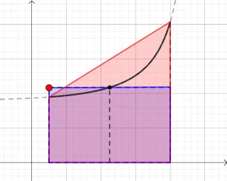
This example demonstrates how to derive upper and lower bounds for a definite integral using a geometric construction and a step (piecewise) function viewpoint. The main math ideas include definite-integral bounding/estimation, relations in isosceles triangles and polygons, and how piecewise/step functions can act as graphical envelopes that approximate the area under a curve. Construction-wise, it uses GeoGebra commands Intersect, Point, Line, Segment, and Polygon to build the key vertices and boundary segments of the geometric configuration; intersections of lines/segments (Intersect) determine critical points. The construction then assembles equation/constraint objects (e.g., eq1, eq2) and parameter-driven quantities (such as i, j, f and the derived f_1, f_2, f_3 together with e_1, e_2) to define the functions or piecewise components used for the integral bounds. It is suitable for advanced high-school enrichment and introductory university calculus, especially for lessons on integral estimates and visually grounded numerical approximation.
GeoGebra Commands & Parameters
Intersect(eq1, xAxis) → EIntersect(eq2, xAxis) → FPoint(eq1) → GLine(G, C) → fIntersect(eq2, f) → HSegment(E, A) → iSegment(F, B) → jPolygon(E, G, H, F) → q1, e, g_1, h_1, f_1Segment(D, C) → kPolygon(A, B, F, E) → q2, a, b, f_2, e_1Polygon(I, J, F, E) → q3, i_1, j_1, f_3, e_2
AI Drawing Prompt Reference
Create a geometry construction diagram for bounding a definite integral. Start by finding two intersection points E and F where two given equations meet the horizontal axis. Mark the point G on the first equation and draw a line through G and a fixed point C; this line intersects the second equation again at H. Connect E to A with a segment and F to B with another segment, then form a polygon q1 with vertices E, G, H, F to represent one envelope boundary. Next, construct two additional polygon envelopes: q2 using A, B, F, E and q3 using I, J, F, E. Include an auxiliary segment k from D to C to complete the key geometric relations showing upper/lower bounds via piecewise-like polygonal enclosures.
The prompt above was compiled from the original drawing commands and is for reference only.