
Four-Engine Aircraft Thrust Analysis
Loading the math board and drawing, please wait…
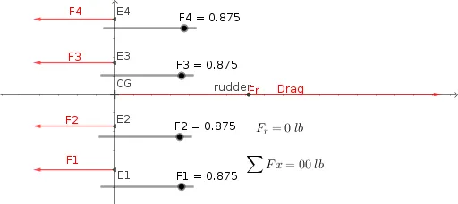
This example demonstrates the force analysis of a four-engine aircraft using a free-body diagram to illustrate the combined effect of engine thrusts and drag on the aircraft's overall forces. Key mathematical concepts include vectors, matrix operations, trigonometric functions, and coordinate geometry. GeoGebra commands like Vector and Intersect are used to construct thrust vectors (F1-F4), the rudder, center of gravity (CG), and drag force. Suitable for high school physics and mathematics education, focusing on vector addition, force equilibrium, and parametric force analysis.
GeoGebra Commands & Parameters
Vector(E, F) → uVector(E1, FE1) → vVector(E2, FE2) → wVector(E3, FE3) → aVector(E4, FE4) → bIntersect(xAxis, yAxis) → CGVector(CG, B) → Drag
AI Drawing Prompt Reference
Draw a coordinate-plane free-body diagram for a four-engine aircraft thrust analysis: set up the x- and y-axes and place the aircraft’s center of gravity at their intersection. From this same CG point, construct four distinct thrust vectors labeled F1, F2, F3, and F4, each drawn as an arrow from CG toward its corresponding endpoint so their directions are clearly shown. Also draw the drag force as a vector starting at the CG point. The four thrust vectors and the drag vector should be displayed together to indicate the combined force effect on the aircraft.
The prompt above was compiled from the original drawing commands and is for reference only.