
Drafting Mechanism Linkage
Loading the math board and drawing, please wait…
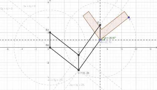
This example demonstrates the working principle of a drafting mechanism linkage. Key mathematical concepts include straight lines, transformations, and geometric constructions. Using GeoGebra commands such as Circle, PointIn, Intersect, etc., a dynamic model of the linkage mechanism can be constructed. Suitable for high school students and teachers.
GeoGebra Commands & Parameters
Circle(B0, DB) → dPointIn(a) → ACircle(A, DA) → cIntersect(d, c) → B, C, ,Line(B0, C) → fLine(B0, B1) → gLine(B1, f) → hLine(C, g) → iIntersect(i, h) → DLine(C, A) → jLine(D, j) → kLine(A, i) → lIntersect(k, l) → EOrthogonalLine(A, l) → mPoint(Circle[A, 5]) → FPolygon(A, F, G, H, I, J) → poly1, a_1, f_1, g_1, h_1, i_1, j_1Segment(B0, C) → nSegment(B1, D) → pSegment(C, A) → qSegment(D, E) → rSegment(B0, B1) → sSegment(C, D) → tSegment(A, E) → bIntersect(c, m) → K, LAngle(K, A, F) → α
AI Drawing Prompt Reference
Draw a drafting mechanism linkage diagram. Start with two fixed base points, draw a large circle centered at one and a small circle at the other, intersecting at two points. Connect the base points to the intersections to form links, then construct parallel and perpendicular auxiliary lines through the intersections to obtain moving pivot points. Connect these pivots back to the base, draw a perpendicular line, place a point on it, and use that point as the center of a hexagon representing the drawing pen. Finally, connect all key points with line segments and mark an angle. The figure shows the geometric relationships of the linkage mechanism.
The prompt above was compiled from the original drawing commands and is for reference only.