
Cylinder Cross Sections: Dynamic Geometry Exploration
Loading the math board and drawing, please wait…
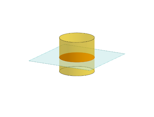
① This GeoGebra example dynamically demonstrates how different cross sections of a cylinder are formed when a plane cuts through it, revealing shapes such as circles, ellipses, and rectangles depending on the plane's orientation. ② Core mathematical concepts include solid geometry (cylinder, cross-section, plane-surface intersection), geometric transformations (translation, rotation), and spatial reasoning, with ties to coordinate geometry. ③ Construction highlights: using Polygon to build the base, Translate and Rotate to generate the cylinder, Plane to define the cutting plane, IntersectPath to compute the intersection curve, OrthogonalLine for perpendicular constructions, and multiple text objects (text1 to text9) to label key points and measurements, making the model highly interactive. ④ Suitable for high school to early college students, this resource aids in teaching solid geometry, enhancing spatial visualization, and serving as a classroom demonstration tool for exploring how cross-section shapes vary with plane angle.
GeoGebra Commands & Parameters
Polygon(B + (-2, -2), B + (2, -2), B + (2, 2), B + (-2, 2)) → poly3, e, f, g, iPointIn(poly3) → CTranslate((0, 0, 0), Vector[B, C]) → APolygon(A + (-4, -4), A + (4, -4), A + (4, 4), A + (-4, 4)) → poly1, a, b, c, dRotate(Rotate[Translate[poly1, Vector[A, A + (0, 0, h)]], (90° * s), A + (0, 0, h), yAxis], (90° * t), A, zAxis) → poly2Rotate(D, 120°, (0, 0, 0)) → EPolygon(D, E, 3, xOyPlane) → poly4, j, k, l, FCylinder((0, 0, 0), (0, 0, 4), 2) → m, e_1, f_1, oPointIn(poly2) → GPointIn(poly2) → HPointIn(poly2) → IPlane(G, I, H) → nIntersectPath(n, m) → poly6OrthogonalLine(A, n) → d_1Ends(m) → g_1, g_1_1