
Cube Construction Demo by cicilia intan
Loading the math board and drawing, please wait…
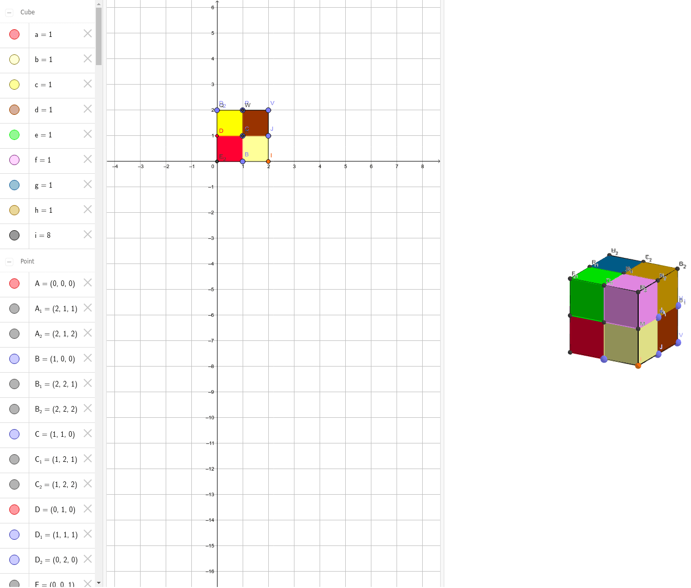
This example demonstrates how to construct a cube and its faces, edges, and vertices using GeoGebra. It involves core math concepts like solid geometry, points, lines, planes, and coordinate geometry. Key GeoGebra commands/objects used include Intersect, Point, and Cube. Suitable for high school and above students to learn about the structure and properties of 3D geometric figures.
GeoGebra Commands & Parameters
Intersect(xAxis, zAxis) → APoint(xAxis) → BPoint(Circle[B, Distance[A, B], Segment[A, B]]) → CCube(A, B, C) → a, D, faceCDHG, faceEFGH, edgeAD, edgeAB, edgeBC, edgeCD_1, edgeAE, edgeDH, edgeEH, edgeEF_1, E, edgeBF, edgeFG, edgeCG, edgeGH, F, G, H, faceABCD, faceADHE, faceABFE, faceBCGFPoint(xAxis) → IPoint(Circle[I, Distance[B, I], Segment[B, I]]) → JCube(B, I, J) → b, K, faceJKON, faceLMNO, edgeBK, edgeBI, edgeIJ, edgeJK, edgeBL, edgeKO, edgeLO, edgeLM, L, edgeIM, edgeMN, edgeJN, edgeNO, M, N, O, faceBIJK, faceBKOL, faceBIML, faceIJNMPoint(Circle[C, Distance[D, C], Segment[D, C]]) → PCube(D, C, P) → c, Q, facePQUT, faceRSTU, edgeDQ, edgeCD, edgeCP, edgePQ, edgeDR, edgeQU, edgeRU, edgeRS, R, edgeCS, edgeST, edgePT, edgeTU, S, T, U, faceCDQP, faceDQUR, faceCDRS, faceCPTSPoint(Circle[J, Distance[C, J], Segment[C, J]]) → VCube(C, J, V) → d, W, face4, face5, edgeCW, edgeCJ, edgeJV, edgeVW, edgeCZ, edge3, edge5, edge4, Z, edge1, edge6, edge2, edge7, A_1, B_1, C_1, faceCJVW, face2, face1, face3Point(Circle[F, Distance[E, F], Segment[E, F]]) → D_1Cube(E, F, D_1) → e, E_1, face10, face11, edge8, edgeEF, edge10, edge12, edge9, edge14, edge16, edge15, F_1, edge11, edge17, edge13, edge18, G_1, H_1, I_1, face6, face8, face7, face9Point(Circle[M, Distance[F, M], Segment[F, M]]) → J_1Cube(F, M, J_1) → f, K_1, face16, face17, edge19, edgeFM, edge21, edge23, edge20, edge25, edge27, edge26, L_1, edge22, edge28, edge24, edge29, M_1, N_1, O_1, face12, face14, face13, face15Point(Circle[D_1, Distance[H, D_1], Segment[H, D_1]]) → P_1Cube(H, D_1, P_1) → g, Q_1, face22, face23, edge31, edge30, edge33, edge35, edge32, edge37, edge39, edge38, R_1, edge34, edge40, edge36, edge41, S_1, T_1, U_1, face18, face20, face19, face21Point(Circle[J_1, Distance[D_1, J_1], Segment[D_1, J_1]]) → V_1Cube(D_1, J_1, V_1) → h, W_1, face28, face29, edge43, edge42, edge45, edge47, edge44, edge49, edge51, edge50, Z_1, edge46, edge52, edge48, edge53, A_2, B_2, C_2, face24, face26, face25, face27Point(Circle[V, Distance[I, V], Segment[I, V]]) → D_2Cube(I, V, D_2) → i, E_2, face34, face35, edge54, edgeIV, edge56, edge58, edge55, edge60, edge62, edge61, F_2, edge57, edge63, edge59, edge64, G_2, H_2, I_2, face30, face32, face31, face33
AI Drawing Prompt Reference
In 3D space, starting from the origin, place a series of points along the x-axis. For each consecutive pair of points, construct a square and extrude it into a cube. These cubes are arranged sequentially along the x-axis, sharing edges or vertices, forming a continuous chain. Each cube clearly shows its six faces, twelve edges, and eight vertices, demonstrating spatial relationships among points, lines, and planes.
The prompt above was compiled from the original drawing commands and is for reference only.