
Crank-Piston: Translation to Rotation Transformation
Loading the math board and drawing, please wait…
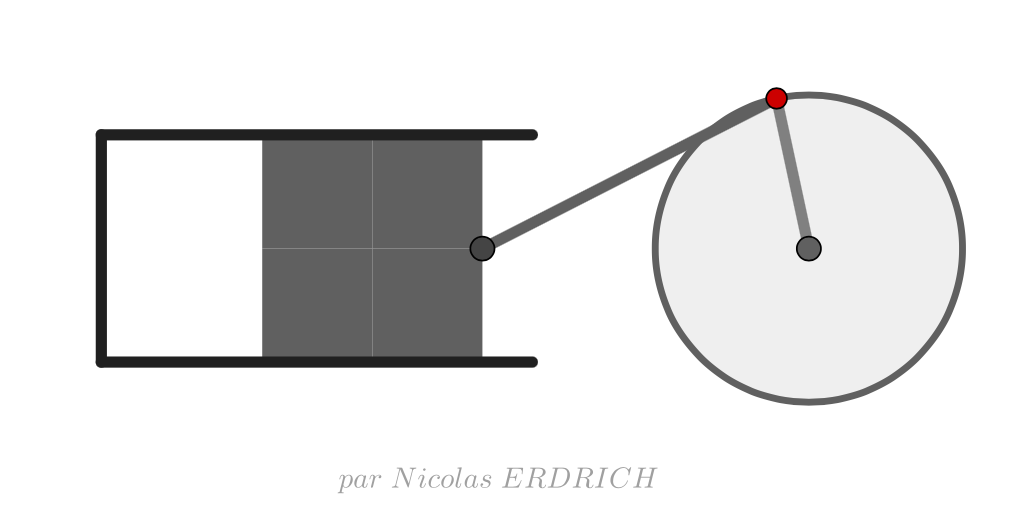
This example demonstrates how the translation of a piston in a crank-piston mechanism is achieved through the rotation of the crank, involving core mathematical concepts like rotation, translation, function graph, integral calculus, intersection, continuity, and probability. It is constructed using commands such as Line, Circle, Point, Distance, Intersect, Segment, Midpoint, Polygon, Mirror, Ray, and OrthogonalLine, making it suitable for high school physics and mathematics education to understand the relationship between mechanical motion and mathematical functions.
GeoGebra Commands & Parameters
Line(O, xAxis) → f_1Circle(O, F_1) → e_1Point(e_1) → GLine(F_1, O) → a_1Distance(F_1, O) → disCircle(G, dis) → ePoint(e_1) → APoint(f_1) → BLine(O, B) → aCircle(A, 12) → cIntersect(c, a, 2) → CSegment(C, A) → bCircle(C, 4) → dLine(C, xAxis) → fIntersect(d, f, 1) → DSegment(D, C) → gMidpoint(b) → EPolygon(D, C, 4) → poly1, h, i, j, k, F, HPolygon(C, D, 4) → poly2, l, m, n, p, I, JMirror(poly1, k) → poly1'Mirror(poly2, m) → poly2'Ray(F, H) → qRay(J, I) → rPoint(q) → KOrthogonalLine(K, q) → sIntersect(s, r) → LLine(M, j) → tPoint(t) → NLine(N, k) → b_1Point(b_1) → PLine(P, t) → c_1OrthogonalLine(M, t) → d_1Intersect(c_1, d_1) → QSegment(M, N) → g_1Segment(N, P) → h_1Segment(P, Q) → i_1Segment(O, A) → j_1
AI Drawing Prompt Reference
Draw a diagram illustrating the translation to rotation transformation in a crank-piston mechanism. Start by creating a circle and a line, marking the center and key points, then use rotation and reflection to form the crank and piston shapes. Determine connection points using geometric relationships and draw corresponding lines and figures to showcase the connection between mechanical motion and mathematical functions.
The prompt above was compiled from the original drawing commands and is for reference only.