
Converging Thick Lens with Principal Planes: A Geometric Imaging Demonstration
Loading the math board and drawing, please wait…
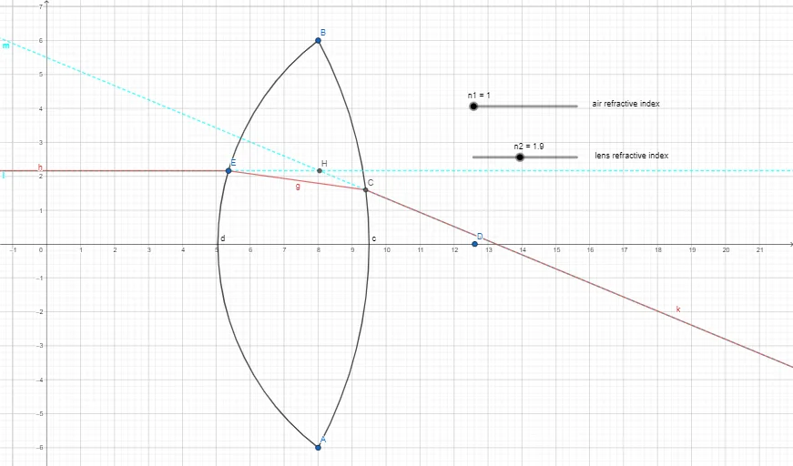
This example demonstrates how a converging thick lens forms an image by constructing an equivalent geometric ray diagram around the principal planes. By building rays, reference lines, and intersection points, it visualizes how incident rays are redirected to meet at an image point, clarifying the relationship between object distance, image distance, and the lens’s principal planes. Key mathematical concepts include geometric construction with points, rays, lines, segments, and angle measurement, where angles (e.g., α, β, γ) constrain the ray configuration; geometric intersection is used to locate the image. The construction leverages GeoGebra commands and objects extracted from the provided summary: Point to define key points (lens-related, object/image points, principal-plane markers), Line/Segment for ray paths and geometric scaffolding, Ray for directed incident rays, CircleArc and Circle for auxiliary curved/curvature-like references, Angle for marking critical angles, Intersect to compute the convergence/image location, and transformations such as Mirror and Rotate for equivalent optical-path construction. Text objects (text1, text2) are used for clear labeling. Suitable for high-school to early university physics/math lessons on geometric optics and for learners using GeoGebra to connect algebraic/functional ideas with visual geometric imaging relationships.
GeoGebra Commands & Parameters
Point(xAxis) → DCircleArc(D, B, A) → dPoint(d) → ERay(D, E) → jMirror(E, yAxis) → E'Ray(E, E') → hPoint(xAxis) → FCircleArc(F, A, B) → cAngle(h, j) → αRotate(D, β, E) → D'Angle(D, E, D') → γSegment(E, D') → fIntersect(c, f, 1) → CSegment(E, C) → gRay(F, C) → iAngle(E, C, F) → δPoint(i) → GRotate(G, (-ϕ), C) → G'Angle(G', C, G) → εRay(C, G') → kLine(E, h) → lLine(C, k) → mIntersect(l, m) → H
AI Drawing Prompt Reference
Draw a geometric imaging demonstration for a converging thick lens on one coordinate plane: include principal-plane reference markers and a horizontal reference axis, then construct two curvature-like circular arcs and choose key points on them to set the ray origins. From the object-related point, draw an incident ray toward the lens area, create an equivalent redirected ray using a mirrored direction with respect to the reference axis, and mark the angle between the incident and equivalent rays as α. Add a rotated corresponding point to generate the angle γ, connect the involved points with reference segments, and determine the image location by finding the intersection of a constructed arc-derived curve with a segment that links the mirrored/rotated construction points. From the other arc side, draw rays that pass through the intersection image point C and extend additional construction lines through C so they meet at a final intersection H. Label key points and key angles such as δ and ε, using clear text annotations.
The prompt above was compiled from the original drawing commands and is for reference only.