
Compass Directions and True Bearing Angle via Geometric Construction
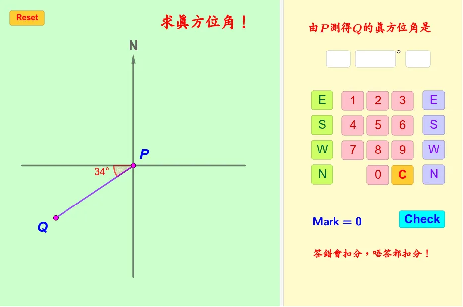
This GeoGebra example demonstrates how a true bearing (true direction/azimuth) can be obtained from a geometric construction by measuring the rotation from a fixed reference direction (e.g., North) to a target direction. It highlights the phenomenon of direction change being represented as a well-defined angle, which can be read directly from the constructed angle objects. The key math concepts include angle definition and measurement, the reference ray (North) versus the target ray/vector, computing the included angle between directions, and using construction tools such as rotation and vector pointing to generate consistent bearing readings across different configurations. Construction is built with GeoGebra commands like Point, Segment, Random, Vector, Circle, Rotate, Angle, Intersect, Textfield, and Length, using objects such as North as the baseline, multiple Angle* displays (e.g., Angle0, Angle1a/Angle2a/Angle3a/Angle4a and related variants), vectors/lines (e.g., LX, YL), and intersections/labels (Intersect, Textfield) to determine directions and present the bearing angles. Suitable for middle school to early undergraduate levels, and useful for integrating mathematical angle construction with navigation/geography-style bearings.
Loading the math board and drawing, please wait…