
Area of Trapezium Demonstration
Loading the math board and drawing, please wait…
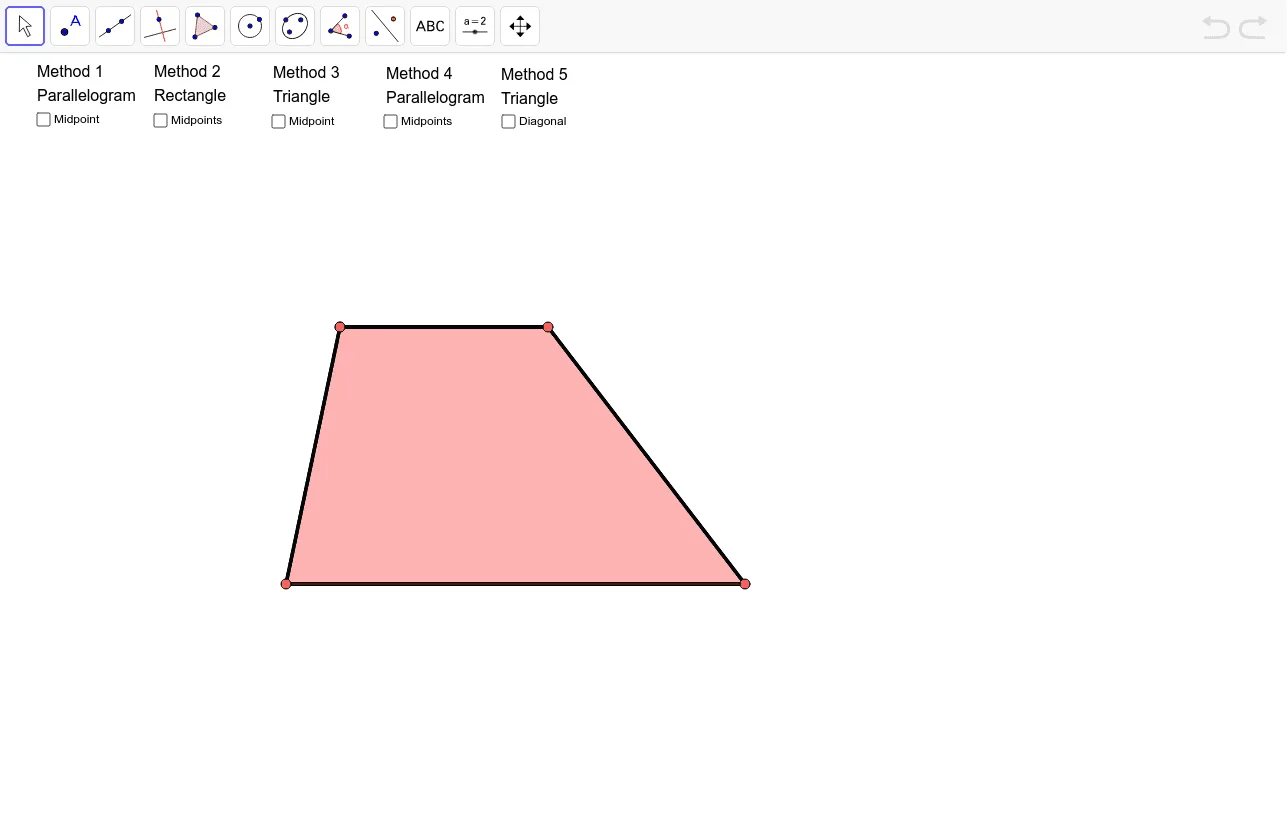
① This example demonstrates the derivation of the trapezium area formula (half the sum of bases times height) through dynamic rotation and rearrangement. ② The core mathematical concept is the area formula for a trapezium, involving properties of polygons, rotation, midpoints, and parallel lines. ③ Construction highlights: using GeoGebra commands such as OrthogonalLine, Point, Line, Segment, Midpoint, Polygon, Rotate, Intersect, and If, the trapezium and its rotated copy are constructed; rotating one part transforms the trapezium into a parallelogram or rectangle, visually proving the area formula. ④ Suitable for middle school geometry lessons, serving as an interactive visual aid for teachers and a self-exploration tool for students to understand the relationship between bases, height, and area.
GeoGebra Commands & Parameters
OrthogonalLine(A, a) → bPoint(b) → BLine(C, b) → cPoint(c) → DSegment(C, A) → dSegment(B, D) → fSegment(A, B) → gSegment(C, D) → hMidpoint(f) → EPolygon(A, B, D, C) → poly1, a_1, b_1, d_1, c_1Rotate(A, Rotate, E) → A'Rotate(B, Rotate, E) → B'Rotate(D, Rotate, E) → D'Rotate(C, Rotate, E) → C'Polygon(A', B', D', C') → poly1', a', b', d', c'Midpoint(C, A) → FMidpoint(B, D) → GOrthogonalLine(F, h) → jOrthogonalLine(G, h) → kIntersect(k, h) → HIntersect(j, h) → IIntersect(k, g) → JIntersect(j, g) → KLine(C, D) → lLine(A, B) → mIntersect(j, l) → LIntersect(k, m) → MIntersect(j, m) → NIntersect(k, l) → OPoint(k) → PPolygon(P, O, D) → poly2, d_2, p, oPoint(j) → QPolygon(N, Q, A) → poly3, a_2, n, qPolygon(B, P, M) → poly4, m_1, b_2, p_1Polygon(Q, L, C) → poly5, c_2, q_1, l_1Rotate(P, α, G) → P'Rotate(O, α, G) → O'Rotate(D, α, G) → D'_1Polygon(P', O', D'_1) → poly2', d'_1, p', o'Rotate(N, α, F) → N'Rotate(Q, α, F) → Q'Rotate(A, α, F) → A'_1Polygon(N', Q', A'_1) → poly3', a'_1, n', q'Rotate(B, (-α), G) → B'_1Rotate(P, (-α), G) → P'_1Rotate(M, (-α), G) → M'Polygon(B'_1, P'_1, M') → poly4', m', b'_1, p'_1Rotate(Q, (-α), F) → Q'_1Rotate(L, (-α), F) → L'Rotate(C, (-α), F) → C'_1Polygon(Q'_1, L', C'_1) → poly5', c'_1, q'_1, l'If(x(A) > x(C), If[x(B) < x(D), Polygon[A, B, G, O, L, F], Polygon[A, M, G, D, L, F]], If[x(B) < x(D), Polygon[N, B, G, O, C, F], Polygon[N, M, G, D, C, F]]) → polyHexIf(x(A) > x(C), If[x(B) < x(D), Polygon[A, B, G, O, L, F], Polygon[A, M, G, D, L, F]], If[x(B) < x(D), Polygon[N, B, G, O, C, F], Polygon[N, M, G, D, C, F]]) → polyHexBorderMidpoint(B, D) → RLine(A, R) → sLine(C, D) → tIntersect(t, s) → SPolygon(A, B, R) → poly6, r_1, a_3, b_3Rotate(A, (-β), R) → A'_2Rotate(B, (-β), R) → B'_2Rotate(R, (-β), R) → R'Polygon(A'_2, B'_2, R') → poly6', r', a'_2, b'_2Polygon(A, C, D, R) → poly7, a_4, c_3, d_3, r_2Polygon(A, R, D, C) → poly8, a_5, r_3, d_4, c_4Polygon(A'_2, B'_2, R) → poly9, r_4, a'_3, b'_3Segment(F, G) → e_1Polygon(F, G, B, A) → poly10, f_1, g_1, b_4, a_6Rotate(F, (-γ), G) → F'Rotate(G, (-γ), G) → G'Rotate(B, (-γ), G) → B'_3Rotate(A, (-γ), G) → A'_3Polygon(F', G', B'_3, A'_3) → poly10', f', g', b'_4, a'_4Polygon(C, F, G, D) → poly11, c_5, f_2, g_2, d_5Midpoint(Bt, Dt) → TPolygon(A, D, B) → poly12, b_5, a_7, d_6Rotate(A, (-δ), T) → A'_4Rotate(D, (-δ), T) → D'_2Rotate(B, (-δ), T) → B'_4Polygon(A'_4, D'_2, B'_4) → poly12', b'_5, a'_5, d'_2Segment(A, D) → h_1Segment(A, D) → i_1Polygon(A, C, D) → poly13, d_7, a_8, c_6Segment(Ah, Dh) → j_1OrthogonalLine(Ah, c) → k_1OrthogonalLine(Dh, c) → n_1Point(k_1) → VPoint(n_1) → WOrthogonalLine(V, c) → t_1OrthogonalLine(W, c) → e_2Intersect(t_1, c) → ZIntersect(e_2, c) → A_1Segment(A_1, Z) → s_1
AI Drawing Prompt Reference
Create an interactive diagram demonstrating the area relation for a trapezium. Start by placing four points and connecting them in order to form the trapezium polygon. Construct key auxiliary elements using perpendicular lines, midpoints on the relevant segments, and intersection points of those lines to create several triangular/polygon regions that will be rearranged. Then apply a dynamic rotation with the same variable angle to the trapezium’s vertices around the specified rotation centers, producing a rotated copy polygon from the rotated points. Ensure the original and rotated shapes are shown together so the area-by-rearrangement idea is visually supported.
The prompt above was compiled from the original drawing commands and is for reference only.