
导数机器
几何画板及绘图内容加载中,请稍等……
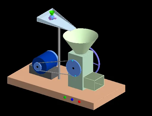
这个范例将导数视为一个操作符,将一个函数转换为另一个函数。通过类比输入输出机器,我们探索了导数的概念。使用GeoGebra命令如Line, Circle, Point等,构建了函数的图像和导数的几何意义。适合高中数学教学,特别是微积分和函数图像的学习。
GeoGebra 命令及参数
Line(O_1, P_1) → f_2Circle(I_2, 1.7, f_2) → d_3Point(d_3) → P_2Polygon(A, B, C, D) → poly1, a_5, b, c, dPrism(poly1, 0.8519331046338638) → e, E, edgeAE, edgeBF, edgeCG, edgeDH, edgeEF, edgeFG, edgeGH, edgeEH, F, G, H, faceABFE, faceBCGF, faceCDHG, faceADHE, faceEFGHPolygon(I, J, K, L) → poly2, i, j, k, lPrism(poly2, 5) → f, M, edgeIM, edgeJN, edgeKO, edgeLP, edgeMN, edgeNO, edgeOP, edgeMP, N, O, P, faceIJNM, faceJKON, faceKLPO, faceILPM, faceMNOPCone(R, Q, 2) → g, h, mPoint(k) → SPoint(k) → VPolygon(S, T, U, V) → poly3, s, t, u, vPrism(poly3, 1.2) → n, W, edge1, edge2, edge3, edge4, edge5, edge6, edge7, edge8, Z, A_1, B_1, face1, face2, face3, face4, face5Prism(face5, -1.2646911609860731) → o, C_1, edge9, edge10, edge11, edge12, edge13, edge15, edge16, edge14, D_1, E_1, F_1, face6, face8, face9, face7, face10Cylinder(G_1, H_1, 1) → p, q, r, wCylinder(I_1, J_1, 1) → a_1, a_2, a_3, a_4Cylinder(K_1, L_1, 0.5) → b_1, c_1, d_1, e_1Cylinder(K_1, L_1, 0.45) → f_1, g_1, h_1, i_1Cylinder(G_1, K_1, 0.15) → j_1, j_2, j_3, j_4Midpoint(O_1, P_1) → R_1Midpoint(K_1, L_1) → T_1Line(K_1, L_1) → n_1Circle(n_1, U_1) → t_1Circle(f_2, S_1) → c_2Tangent(c_2, t_1) → r_1, s_1, g_2, h_2Intersect(-6.4380165289256395x² + 61.98347107438032x y - 128.132231404959y² - 10.04132231404962x + 41.838842975206745y = 3.388946280991749, x² + y² = 0.8100000000000006) → , , ,Intersect(s_1, c_2) → V_1, W_1Intersect(s_1, t_1) → Z_1, A_2Intersect(r_1, t_1) → B_2, C_2Intersect(r_1, c_2) → D_2, E_2Segment(A_2, W_1) → i_2Segment(C_2, E_2) → l_2Circle(G_2, 0.15) → d_2Polygon((x(G_2) - 2, y(G_2) - 1.5, 8), (x(G_2) + 2, y(G_2) - 0.5, 7.5), (x(G_2) + 2, y(G_2) + 0.5, 7.5), (x(G_2) - 2, y(G_2) + 1.5, 8)) → poly4, m_2, n_2, p_2, q_2Polygon((x(G_2) - 2, y(G_2) - 1.5, 8), (x(G_2) - 2, y(G_2) - 1.5, 8.5), (x(G_2) - 2, y(G_2) + 1.5, 8.5), (x(G_2) - 2, y(G_2) + 1.5, 8)) → poly5, r_2, s_2, t_2, b_2Polygon((x(G_2) - 2, y(G_2) - 1.5, 8), (x(G_2) + 2, y(G_2) - 0.5, 7.5), (x(G_2) - 2, y(G_2) - 1.5, 8.5)) → poly6, f_3, g_3, h_3Polygon((x(G_2) - 2, y(G_2) + 1.5, 8), (x(G_2) + 2, y(G_2) + 0.5, 7.5), (x(G_2) - 2, y(G_2) + 1.5, 8.5)) → poly7, i_3, l_3, m_3Cylinder(d_2, 7.6) → u_1, u_2, u_3Cylinder(M_1, O_1, 0.1) → o_1, e_2, c_3, v_1Rotate(P_2, a / 2, f_2) → J_2Rotate(J_2, π / 3, f_2) → K_2Rotate(K_2, π / 3, f_2) → L_2Rotate(L_2, π / 3, f_2) → M_2Rotate(M_2, π / 3, f_2) → N_2Rotate(N_2, π / 3, f_2) → O_2Cylinder(I_2, J_2, 0.05) → w_2, q_3, r_3, v_2Cylinder(I_2, O_2, 0.05) → w_1, w_4, w_5, w_6Cylinder(I_2, M_2, 0.05) → w_3, w_7, w_8, w_9Cylinder(I_2, L_2, 0.05) → o_3, o_3, o_4, o_5Cylinder(I_2, N_2, 0.05) → g_4, g_5, g_6, g_7Cylinder(I_2, K_2, 0.05) → b_3, b_4, b_5, b_6Cylinder(O_1, P_1, 1) → l_1, l_4, l_5, l_6Cylinder(O_1, P_1, 0.9) → k_1, k_2, k_3, k_4Rotate(A_2, a, n_1) → Q_2Rotate(C_2, a, n_1) → T_2Rotate(W_1, a / 2, f_2) → S_2Rotate(E_2, a / 2, f_2) → R_2Dilate(A_2, p_1, W_1) → V_2Dilate(C_2, (-p_1) - 0.5, E_2) → W_2Cylinder(I_2, O_1, 0.15) → q_1, q_4, q_5, q_6Line(A_3, xAxis) → n_3Point(n_3) → B_3OrthogonalLine(B_3, n_3) → p_3OrthogonalLine(A_3, n_3) → s_3Point(s_3) → C_3OrthogonalLine(C_3, s_3) → t_3Intersect(p_3, t_3) → D_3Polygon(A_3, B_3, D_3, C_3) → poly8, a_6, b_7, d_4, c_4Prism(poly8, 1.8) → o_2, E_3, edge17, edge18, edge19, edge20, edge21, edge22, edge23, edge24, F_3, G_3, H_3, face11, face12, face13, face14, face15Midpoint(n_2) → J_3Line(R, (0, 0, 0)) → f_4Line(J_3, f_4) → h_4Point(h_4) → L_3Dilate(L_3, v_3 - 1, J_3) → M_3Midpoint(B_1, C_1) → N_3Line(N_3, edgeEH) → i_4Point(i_4) → O_3Line(I_3, Q_3) → e_3Dilate(Q_3, v_3, I_3) → K_3Textfield(p_4) → InputBox2Dilate(O_3, (v_3 - 3) / 2, N_3) → P_3PointIn(faceKLPO) → T_3OrthogonalLine(T_3, faceKLPO) → s_4Line(K_3, edgeNO) → f_5Line(K_3, edgeLP) → h_5Sphere(K_3, 0.3) → d_5Point(h_5) → V_3Cone(V_3, K_3, 0.3) → e_5, k_5, i_5Point(f_5) → W_3Cylinder(K_3, W_3, 0.1) → j_5, p_5, r_5, m_5Sphere(M_3, 0.3) → s_5Line(M_3, h_5) → f_6Point(f_6) → Z_3Cone(Z_3, M_3, 0.3) → u_5, c_6, v_5Line(M_3, f_5) → h_6Point(h_6) → A_4Cylinder(M_3, A_4, 0.1) → d_6, e_6, k_6, i_6Line(K_3, edgeOP) → j_6Point(j_6) → B_4Line(M_3, edgeOP) → m_6Point(m_6) → C_4Circle(B_4, 0.2, j_6) → p_6Circle(C_4, 0.2, m_6) → r_6Line(P_3, edgeLP) → n_6Point(n_6) → D_4Midpoint(D_4, P_3) → E_4Cylinder(D_4, P_3, 0.3) → o_6, s_6, c_7, u_6Point(n_6) → F_4Cone(F_4, E_4, 0.3) → v_6, d_7, a_7Line(E_4, i_4) → f_7Point(f_7) → G_4Cylinder(E_4, G_4, 0.1) → e_7, h_7, k_7, i_7Line(E_4, edgeOP) → j_7Point(j_7) → H_4Circle(H_4, 0.2, j_7) → p_7Midpoint(edge6) → I_4Line(I_4, edge7) → l_7Line(P_3, edge11) → m_7Intersect(m_7, l_7) → J_4Vector(P_3, J_4) → u_7Translate(o_6, u_7) → n_7Translate(a_7, u_7) → o_7Translate(p_7, u_7) → q_7Translate(i_7, u_7) → r_7Derivative(p_4) → dr
AI 绘图提示语参考
画一个函数的图像,并展示其导数的几何意义。首先绘制函数曲线,然后以曲线为边界画一个圆,圆心在曲线上。接着,以圆为边界画一个柱体,柱体中心轴线与曲线相切。再以柱体为基础,向上延伸出多个小的锥体,形成类似阶梯的结构。最后,在柱体侧面添加多个小的圆柱体,使整体结构更加丰富。
以上提示语为根据原始绘图命令整理而来,仅供参考。