
立方体部分演示 by Renáta Vágová (5)
几何画板及绘图内容加载中,请稍等……
所属专题
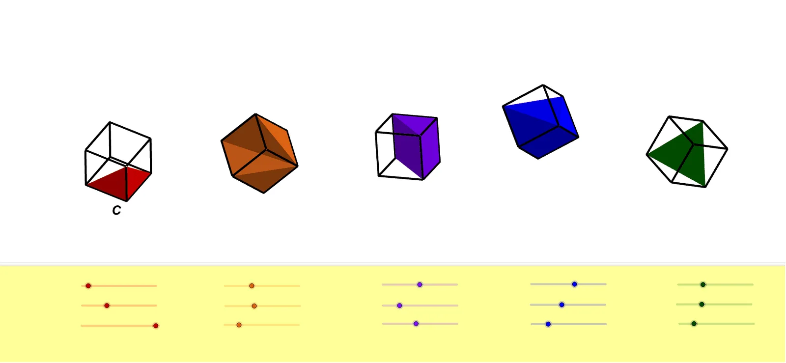
TWO PARTS OF A CUBE
①本范例演示立方体的不同部分及其几何关系;②涉及核心数学概念包括立体几何、多边形、线性规划与对数运算;③构造过程中运用了点、立方体、交点、线、旋转、多边形、金字塔等 GeoGebra 命令与对象;④适合高中及以上学生用于理解空间几何与优化问题。
GeoGebra 命令及参数
Point(xAxis) → APoint(xAxis) → BPoint(Circle[B, Distance[A, B], Segment[A, B]]) → CCube(A, B, C) → a, D, faceCDHG, faceEFGH, edgeAD, edgeAB, edgeBC, edgeCD, edgeAE, edgeDH, edgeEH, edgeEF, E, edgeBF, edgeFG, edgeCG, edgeGH, F, G, H, faceABCD, faceADHE, faceABFE, faceBCGFPoint(xAxis) → IPoint(xAxis) → JPoint(Circle[J, Distance[I, J], Segment[I, J]]) → KCube(I, J, K) → b, L, faceKLPO, faceMNOP, edgeIL_1, edgeIJ_1, edgeJK_1, edgeKL_1, edgeIM_1, edgeLP_1, edgeMP_1, edgeMN_1, M, edgeJN_1, edgeNO, edgeKO, edgeOP, N, O, P, faceIJKL, faceILPM_1, faceIJNM_1, faceJKONIntersect(yAxis, xAxis) → QPoint(xAxis) → RPoint(Circle[R, Distance[Q, R], Segment[Q, R]]) → SCube(Q, R, S) → c, T, faceSTZW, faceUVWZ, edgeQT_1, edgeQR, edgeRS_1, edgeST_1, edgeQU, edgeTZ, edgeUZ, edgeUV, U, edgeRV_1, edgeVW_1, edgeSW_1, edgeWZ, V, W, Z, faceQRST, faceQTZU, faceQRVU, faceRSWVPoint(xAxis) → A_1Point(xAxis) → B_1Point(Circle[B_1, Distance[A_1, B_1], Segment[A_1, B_1]]) → C_1Cube(A_1, B_1, C_1) → d, D_1, face5, face6, edge2, edge1, edge4, edge6, edge3, edge8, edge10, edge9, E_1, edge5, edge11, edge7, edge12, F_1, G_1, H_1, face1, face3, face2, face4Point(xAxis) → I_1Point(xAxis) → J_1Point(Circle[J_1, Distance[I_1, J_1], Segment[I_1, J_1]]) → K_1Cube(I_1, J_1, K_1) → e, L_1, face11, face12, edge14, edge13, edge16, edge18, edge15, edge20, edge22, edge21, M_1, edge17, edge23, edge19, edge24, N_1, O_1, P_1, face7, face9, face8, face10Line(A, yAxis) → fLine(I, yAxis) → gLine(A_1, yAxis) → hLine(I_1, yAxis) → iLine(A, zAxis) → jLine(I, zAxis) → kLine(A_1, zAxis) → lLine(I_1, zAxis) → mRotate(a, α, f) → a'Rotate(a', β, xAxis) → a''Rotate(a'', γ, j) → a'''Rotate(b, δ, g) → b'Rotate(b', ε, xAxis) → b''Rotate(b'', ζ, k) → b'''Rotate(c, (-η), yAxis) → c'Rotate(c', θ, xAxis) → c''Rotate(c'', ι, zAxis) → c'''Rotate(d, κ, h) → d'Rotate(d', λ, xAxis) → d''Rotate(d'', μ, l) → d'''Rotate(e, ν, i) → e'Rotate(e', ξ, xAxis) → e''Rotate(e'', ο, m) → e'''Polygon(B, G, E) → t1, e_1, b_1, g_1Polygon(E, B, F) → t2, f_1, e_2, b_2Polygon(E, F, G) → t3, g_2, e_3, f_2Polygon(B, G, F) → t4, f_3, b_3, g_3Rotate(t1, α, f) → t1'Rotate(t1', β, xAxis) → t1''Rotate(t1'', γ, j) → t1'''Rotate(t3, α, f) → t3'Rotate(t3', β, xAxis) → t3''Rotate(t3'', γ, j) → t3'''Rotate(t4, α, f) → t4'Rotate(t4', β, xAxis) → t4''Rotate(t4'', γ, j) → t4'''Rotate(t2, α, f) → t2'Rotate(t2', β, xAxis) → t2''Rotate(t2'', γ, j) → t2'''Pyramid(L, I, M, P, K) → n, faceILPM, edgeKL, edgeIK_1, edgeKM_1, edgeKP, faceIKL, faceIKM_1, faceKMP, faceKLP, edgeIL, edgeIM_2, edgeMP, edgeLPPyramid(M, I, J, N, K) → o, faceIJNM, edgeKM, edgeIK, edgeJK, edgeKN, faceIKM, faceIJK, faceJKN, faceKMN, edgeIM, edgeIJ, edgeJN, edgeMNRotate(n, δ, g) → n'Rotate(n', ε, xAxis) → n''Rotate(n'', ζ, k) → n'''Rotate(o, δ, g) → o'Rotate(o', ε, xAxis) → o''Rotate(o'', ζ, k) → o'''Point(c''') → Q_1Pyramid(Q, Q_1, R, S, T, W) → p, face15, edgeST, edgeQT, edgeQW, edge27, edgeRW_1, edgeSW, edgeTW, face13, face14, faceRSW, faceSTW, faceQTW, edge25, edge26, edgeRSPyramid(Q_1, R, W, V) → q, face17, edgeVW, face16, faceRVW, face18, edge28, edgeRW, edge30, edge29, edgeRVRotate(p, (-η), yAxis) → p'Rotate(p', θ, xAxis) → p''Rotate(p'', ι, zAxis) → p'''Rotate(q, (-η), yAxis) → q'Rotate(q', θ, xAxis) → q''Rotate(q'', ι, zAxis) → q'''Pyramid(A_1, B_1, C_1, D_1, F_1) → r, face23, edge33, edge35, edge37, edge38, face19, face21, face22, face20, edge31, edge34, edge36, edge32Pyramid(D_1, A_1, E_1, H_1, F_1) → s, face28, edge42, edge41, edge44, edge46, face24, face25, face27, face26, edge39, edge40, edge45, edge43Pyramid(C_1, D_1, H_1, F_1) → t, face30, edge52, face29, face32, face31, edge47, edge51, edge49, edge48, edge50Rotate(r, κ, h) → r'Rotate(r', λ, xAxis) → r''Rotate(r'', μ, l) → r'''Rotate(s, κ, h) → s'Rotate(s', λ, xAxis) → s''Rotate(s'', μ, l) → s'''Rotate(t, κ, h) → t'Rotate(t', λ, xAxis) → t''Rotate(t'', μ, l) → t'''Pyramid(L_1, I_1, J_1, M_1) → u, face33, edge57, face35, face34, face36, edge54, edge53, edge56, edge58, edge55Rotate(u, ν, i) → u'Rotate(u', ξ, xAxis) → u''Rotate(u'', ο, m) → u'''
AI 绘图提示语参考
绘制一个立方体,展示其不同部分和几何关系。首先画出三个立方体,每个立方体由三个点确定,这些点位于x轴上且等距分布。接着,在y轴和z轴上分别画出三条线,并将每个立方体绕这些线旋转,得到不同的视角。最后,连接立方体的顶点,形成多个多边形面,突出显示立方体的结构和空间关系。
以上提示语为根据原始绘图命令整理而来,仅供参考。