
三维曲面绘制器:分块显示
几何画板及绘图内容加载中,请稍等……
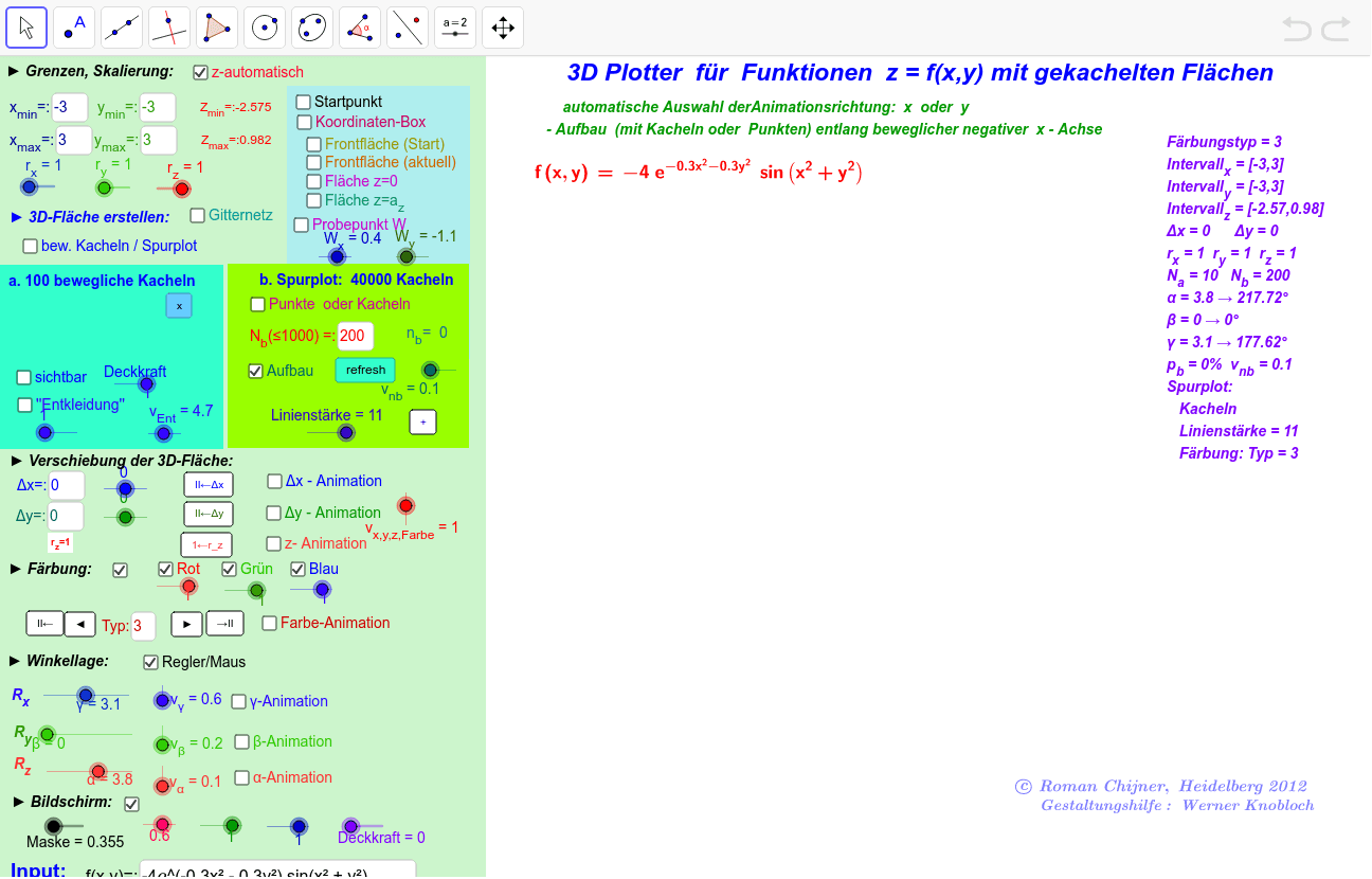
该范例演示了如何使用分块显示技术绘制三维曲面。核心数学概念包括函数、解析几何和微积分。使用了如序列、点、向量、多边形等GeoGebra对象和命令。适合高中及以上学生或教师使用。
GeoGebra 命令及参数
Corner(1) → Eckpunkt1Corner(2) → Eckpunkt2If(c, α, x(C - Eckpunkt1) / dEx * c_{Move}) → α1Mod(α1, 6.283) → α2Corner(3) → Eckpunkt3If(c, β, y(C - Eckpunkt2) / dEy * c_{Move}) → β1Mod(β1, 6.283) → β2Sequence(a11 * Element[zWX1, i] + a12 * Element[zWY1, i] + a13 * Element[zWZ1, i], i, 1, 4) → zWX1'Element(zWW_0, 3) → zW_2Element(zWW_0, 4) → zW_1If(zW_1 ≟ 4 ∧ zW_2 ≟ 1 ∨ zW_1 ≟ 1 ∧ zW_2 ≟ 4, true, false) → dBB3If(zW_1 ≟ 2 ∧ zW_2 ≟ 3 ∨ zW_1 ≟ 3 ∧ zW_2 ≟ 2, true, false) → dBB4If(dBB3 ∨ dBB4, true, false) → ddd1If(zW_1 ≟ 1 ∧ zW_2 ≟ 2 ∨ zW_1 ≟ 2 ∧ zW_2 ≟ 1, true, false) → dBB1If(dBB1 ∨ dBB4, true, false) → ddd2Join(Sequence[Sequence[(x_{min} + If[ddd1, i, j] * dx_1, y_{min} + If[ddd1, j, i] * dy_1), i, If[ddd2, 0, N], If[ddd2, N, 0], If[ddd2, 1, -1]], j, If[ddd2, 0, N], If[ddd2, N, 0], If[ddd2, 1, -1]]) → l1aaIf(b, Min[RemoveUndefined[Sequence[f(x(Element[l1aa, i]) - Δx, y(Element[l1aa, i]) - Δy), i, 1, lä]]], z_{min}) → zz_{min}If(b, Max[RemoveUndefined[Sequence[f(x(Element[l1aa, i]) - Δx, y(Element[l1aa, i] - Δy)), i, 1, lä]]], z_{max}) → zz_{max}If(ccc1, N_0, 2) → N_PIf(ddd1, Sequence[Element[x2la, If[ddd2, n_b - 1, N_P + 2 - n_b + 1]] + 0 * i, i, 1, N_P + 1], x2la) → Y0_pIf(ddd1, x1la, Sequence[Element[x1la, If[ddd2, n_b - 1, N_P + 2 - n_b + 1]] + 0 * i, i, 1, N_P + 1]) → X0_pIf(ddd1, x1la, Sequence[Element[x1la, If[ddd2, n_b, N_P + 2 - n_b]] + 0 * i, i, 1, N_P + 1]) → X_pIf(ddd1, Sequence[Element[x2la, If[ddd2, n_b, N_P + 2 - n_b]] + 0 * i, i, 1, N_P + 1], x2la) → Y_pSequence(f(Element[X0_p, i] - Δx, Element[Y0_p, i] - Δy), i, 1, N_P + 1) → Z0_pSequence(f(Element[X_p, i] - Δx, Element[Y_p, i] - Δy), i, 1, N_P + 1) → Z_pIf(abs(x) < 0.2, 0.2, x) → hIf(ddd1, x_{max}, y_{max}) → tb'If(ddd1, x_{min}, y_{min}) → ta'If(ddd1, y_{min}, x_{min}) → taIf(ddd1, y_{max}, x_{max}) → tbElement(zWW_0, 2) → zW_3If(zW_1 ≟ 3 ∧ zW_2 ≟ 4 ∨ zW_1 ≟ 4 ∧ zW_2 ≟ 3, true, false) → dBB2Polygon(Eckpunkt1, Eck11, Eck12, (x(Eckpunkt1), y(Eck12))) → Vieleck2, eckpunkt1, eck11, eck12, a_1Sequence(Segment[Element[zTT1, i], Element[zTT1, i + 1]], i, 1, 7) → BoxStrVector(Element[zTT1, 4], Element[zTT1, 1]) → zVectxVector(Element[zTT1, 4], Element[zTT1, 3]) → zVectyVector(Element[zTT1, 4], Element[zTT1, 5]) → zVectzPolygon(Eck11, Eckpunkt2, Eckpunkt3, Eck12) → Vieleck1, eck11_1, eckpunkt2, eckpunkt3, eck12_1Element(zTT, zW_1) → zY1Element(zTT, zW_2) → zY2Element(zTT, zW_3) → zY3Polygon(zTT) → zTTPoly, , , ,Element(zWW_0, 1) → zW_4Element(zTT1, 7) → P_RElement(zTT1, 8) → P_LPolygon({Element[zTT1, 1], Element[zTT1, 2], Element[zTT1, 7], Element[zTT1, 8]}) → Vvrd0, , , ,Segment(P_R, P_L) → StrRLPolygon(Sequence[Element[zTT1, i], i, 9, 12]) → zlPoly, n, r, s, c_1Ray(B, Element[zTT1, 13]) → StrxRay(B, Element[zTT1, 14]) → StryRay(B, Element[zTT1, 15]) → StrzTextfield(N) → inputBox1Textfield(x_{min}) → inputBox5Textfield(x_{max}) → inputBox6Textfield(y_{min}) → inputBox7Textfield(y_{max}) → inputBox8Textfield(z_{min}) → inputBox9Textfield(z_{max}) → inputBox10Textfield(n_a) → Textfeld1Textfield(v_{na}) → Textfeld3Textfield(v_{ne}) → Textfeld4Textfield(n_e) → Textfeld2Point(yAxis) → HorizontOrthogonalLine(Horizont, yAxis) → horizontPoint(xAxis) → VertikalOrthogonalLine(Vertikal, xAxis) → vertikalElement(zTT1, zW_1) → zlN11Element(zTT1, 9 - zW_1) → zlN111Element(zTT1, zW_2) → zlN22Element(zTT1, 9 - zW_2) → zlN222Polygon({zlN11, zlN22, zlN222, zlN111}) → Vgrund01, , , ,If(g, m * (N + 1), N * (N + 1)) → tttSequence(If[i ≟ ceil(i / (N + 1)) * (N + 1), Polygon[(0, 0), (0, 0), (0, 0), (0, 0)], Polygon[Element[ylPunkten10, i], Element[ylPunkten10, i + N + 1], Element[ylPunkten10, i + N + 2], Element[ylPunkten10, i + 1]]], i, 1, ttt) → yylPolyyTextfield(Typ) → Textfeld5Element(ylPunkten101, m1) → zPTextfield(N_0) → inputBox3Polygon(B, Element[zTT1, 16], Element[zTT1, 17], Element[zTT1, 20]) → Strecke4Eck, b_2, d_1, h_1, i_1Segment(Element[zTT1, 18], Element[zTT1, 19]) → StrzxySegment(Element[zTT1, 18], Element[zTT1, 17]) → StrzzElement(zTT1, 18) → WSegment(B, Element[zTT1, 19]) → j_1Element(zTT1, 20) → PWyElement(zTT1, 16) → PWxElement(zTT1, 19) → PWzPolygon(Element[ylPunkten100, m1], Element[ylPunkten100, m1 + 1], Element[ylPunkten101, m1 + 1], Element[ylPunkten101, m1]) → zV1, z01, z04, z03, z02Textfield(Δx) → Textfeld6Textfield(Δy) → Textfeld7LaTeX(f, true, true) → Text14Textfield(f) → Textfeld8Element(yylPolyy, 1) → M_{1}Element(yylPolyy, 2) → M_{2}Element(yylPolyy, 3) → M_{3}Element(yylPolyy, 4) → M_{4}Element(yylPolyy, 5) → M_{5}Element(yylPolyy, 6) → M_{6}Element(yylPolyy, 7) → M_{7}Element(yylPolyy, 8) → M_{8}Element(yylPolyy, 9) → M_{9}Element(yylPolyy, 10) → M_{10}Element(yylPolyy, 11) → M_{11}Element(yylPolyy, 12) → M_{12}Element(yylPolyy, 13) → M_{13}Element(yylPolyy, 14) → M_{14}Element(yylPolyy, 15) → M_{15}Element(yylPolyy, 16) → M_{16}Element(yylPolyy, 17) → M_{17}Element(yylPolyy, 18) → M_{18}Element(yylPolyy, 19) → M_{19}Element(yylPolyy, 20) → M_{20}Element(yylPolyy, 21) → M_{21}Element(yylPolyy, 22) → M_{22}Element(yylPolyy, 23) → M_{23}Element(yylPolyy, 24) → M_{24}Element(yylPolyy, 25) → M_{25}Element(yylPolyy, 26) → M_{26}Element(yylPolyy, 27) → M_{27}Element(yylPolyy, 28) → M_{28}Element(yylPolyy, 29) → M_{29}Element(yylPolyy, 30) → M_{30}Element(yylPolyy, 31) → M_{31}Element(yylPolyy, 32) → M_{32}Element(yylPolyy, 33) → M_{33}Element(yylPolyy, 34) → M_{34}Element(yylPolyy, 35) → M_{35}Element(yylPolyy, 36) → M_{36}Element(yylPolyy, 37) → M_{37}Element(yylPolyy, 38) → M_{38}Element(yylPolyy, 39) → M_{39}Element(yylPolyy, 40) → M_{40}Element(yylPolyy, 41) → M_{41}Element(yylPolyy, 42) → M_{42}Element(yylPolyy, 43) → M_{43}Element(yylPolyy, 44) → M_{44}Element(yylPolyy, 45) → M_{45}Element(yylPolyy, 46) → M_{46}Element(yylPolyy, 47) → M_{47}Element(yylPolyy, 48) → M_{48}Element(yylPolyy, 49) → M_{49}Element(yylPolyy, 50) → M_{50}Element(yylPolyy, 51) → M_{51}Element(yylPolyy, 52) → M_{52}Element(yylPolyy, 53) → M_{53}Element(yylPolyy, 54) → M_{54}Element(yylPolyy, 55) → M_{55}Element(yylPolyy, 56) → M_{56}Element(yylPolyy, 57) → M_{57}Element(yylPolyy, 58) → M_{58}Element(yylPolyy, 59) → M_{59}Element(yylPolyy, 60) → M_{60}Element(yylPolyy, 61) → M_{61}Element(yylPolyy, 62) → M_{62}Element(yylPolyy, 63) → M_{63}Element(yylPolyy, 64) → M_{64}Element(yylPolyy, 65) → M_{65}Element(yylPolyy, 66) → M_{66}Element(yylPolyy, 67) → M_{67}Element(yylPolyy, 68) → M_{68}Element(yylPolyy, 69) → M_{69}Element(yylPolyy, 70) → M_{70}Element(yylPolyy, 71) → M_{71}Element(yylPolyy, 72) → M_{72}Element(yylPolyy, 73) → M_{73}Element(yylPolyy, 74) → M_{74}Element(yylPolyy, 75) → M_{75}Element(yylPolyy, 76) → M_{76}Element(yylPolyy, 77) → M_{77}Element(yylPolyy, 78) → M_{78}Element(yylPolyy, 79) → M_{79}Element(yylPolyy, 80) → M_{80}Element(yylPolyy, 81) → M_{81}Element(yylPolyy, 82) → M_{82}Element(yylPolyy, 83) → M_{83}Element(yylPolyy, 84) → M_{84}Element(yylPolyy, 85) → M_{85}Element(yylPolyy, 86) → M_{86}Element(yylPolyy, 87) → M_{87}Element(yylPolyy, 88) → M_{88}Element(yylPolyy, 89) → M_{89}Element(yylPolyy, 90) → M_{90}Element(yylPolyy, 91) → M_{91}Element(yylPolyy, 92) → M_{92}Element(yylPolyy, 93) → M_{93}Element(yylPolyy, 94) → M_{94}Element(yylPolyy, 95) → M_{95}Element(yylPolyy, 96) → M_{96}Element(yylPolyy, 97) → M_{97}Element(yylPolyy, 98) → M_{98}Element(yylPolyy, 99) → M_{99}Element(yylPolyy, 100) → M_{100}Element(yylPolyy, 101) → M_{101}Element(yylPolyy, 102) → M_{102}Element(yylPolyy, 103) → M_{103}Element(yylPolyy, 104) → M_{104}Element(yylPolyy, 105) → M_{105}Element(yylPolyy, 106) → M_{106}Element(yylPolyy, 107) → M_{107}Element(yylPolyy, 108) → M_{108}Element(yylPolyy, 109) → M_{109}Element(yylPolyy, 110) → M_{110}
AI 绘图提示语参考
绘制一个3D曲面图,并使用瓷砖显示方式展示。首先定义坐标系中的三个关键点Eckpunkt1、Eckpunkt2和Eckpunkt3,然后通过一系列变换和条件语句生成一系列点和线段,最终形成一个3D曲面。注意调整参数以适应不同视图。
以上提示语为根据原始绘图命令整理而来,仅供参考。