
Visibility Experiment: See What the Gray Dot Sees
Loading the math board and drawing, please wait…
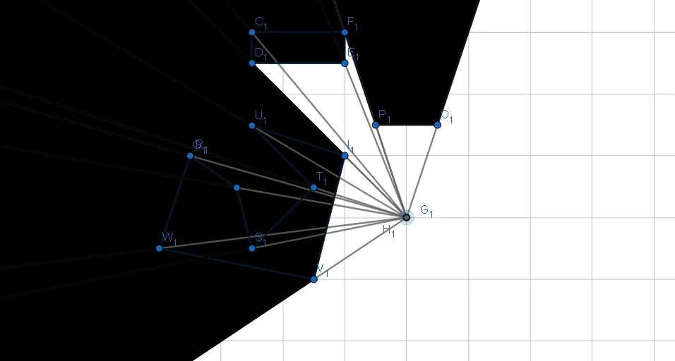
① This interactive example demonstrates a visibility experiment where only the region visible to a gray dot is shown, illustrating the concept of line-of-sight and occlusion. ② Core mathematical concepts include visibility, occlusion, polygons, angles, and geometric transformations, involving basic elements such as points, line segments, polygons, and circles. ③ Construction uses GeoGebra commands: Polygon, Ray, Intersect, Circle, and Segment; objects include multiple points (A1 to N1), segments (c1 to n2), polygons (q1 to q5), and circles, with ray-polygon intersections computing the visible area dynamically. ④ Suitable for middle/high school geometry lessons, math lab activities, or introductory computer graphics, helping students understand spatial perception and geometric visualization, and explore mathematical modeling of occlusion problems.
GeoGebra Commands & Parameters
Polygon(C_{1}, D_{1}, E_{1}, F_{1}) → q1_{1}, c_{1}, d_{1}, e_{1}, f_{2}Ray(G_{1}, E_{1}) → g_{1}Ray(G_{1}, D_{1}) → h_{1}Ray(G_{1}, C_{1}) → i_{1}Intersect(g_{1}, i_{1}) → H_{1}Ray(G_{1}, F_{1}) → j_{1}Circle(I_{1}, J_{1}) → f_{1}Intersect(f_{1}, i_{1}, 1) → K_{1}Intersect(f_{1}, j_{1}, 1) → L_{1}Intersect(f_{1}, g_{1}, 1) → M_{1}Intersect(f_{1}, h_{1}, 1) → N_{1}Polygon(L_{1}, F_{1}, C_{1}, K_{1}) → q2_{1}, l_{1}, f_{3}, c_{2}, k_{1}Polygon(D_{1}, N_{1}, K_{1}, C_{1}) → q3_{1}, d_{2}, n_{1}, k_{2}, c_{3}Polygon(N_{1}, M_{1}, E_{1}, D_{1}) → q4_{1}, n_{2}, m_{1}, e_{2}, d_{3}Polygon(F_{1}, L_{1}, M_{1}, E_{1}) → q5_{1}, f_{4}, l_{2}, m_{2}, e_{3}Segment(O_{1}, P_{1}) → p_{1}Ray(G_{1}, P_{1}) → q_{1}Ray(G_{1}, O_{1}) → r_{1}Polygon(Q_{1}, R_{1}, S_{1}, T_{1}, U_{1}, I_{1}, V_{1}, W_{1}) → poly1_{1}, q_{2}, r_{2}, s_{1}, t_{1}, u_{1}, i_{2}, v_{1}, w_{1}Intersect(f_{1}, r_{1}, 1) → Z_{1}Intersect(f_{1}, q_{1}, 1) → A_{2}Polygon(Z_{1}, A_{2}, P_{1}, O_{1}) → q6_{1}, z_{1}, a_{2}, p_{2}, o_{1}Ray(G_{1}, U_{1}) → a_{1}Ray(G_{1}, Q_{1}) → b_{1}Ray(G_{1}, R_{1}) → g_{2}Ray(G_{1}, W_{1}) → h_{2}Ray(G_{1}, S_{1}) → j_{2}Ray(G_{1}, T_{1}) → s_{2}Ray(G_{1}, I_{1}) → t_{2}Ray(G_{1}, V_{1}) → b_{2}Intersect(f_{1}, h_{2}, 1) → B_{2}Intersect(f_{1}, b_{1}, 1) → C_{2}Polygon(W_{1}, B_{2}, C_{2}, Q_{1}) → q7_{1}, w_{2}, g_{3}, h_{3}, q_{3}Intersect(f_{1}, g_{2}, 1) → D_{2}Polygon(Q_{1}, C_{2}, D_{2}, R_{1}) → q8_{1}, q_{4}, i_{3}, j_{3}, r_{3}Intersect(f_{1}, j_{2}, 1) → E_{2}Polygon(D_{2}, E_{2}, S_{1}, R_{1}) → q9_{1}, k_{3}, l_{3}, s_{3}, r_{4}Intersect(f_{1}, s_{2}, 1) → F_{2}Polygon(S_{1}, E_{2}, F_{2}, T_{1}) → q10_{1}, s_{4}, m_{3}, n_{3}, t_{3}Intersect(f_{1}, a_{1}, 1) → G_{2}Polygon(T_{1}, F_{2}, G_{2}, U_{1}) → q11_{1}, t_{4}, p_{3}, a_{3}, u_{2}Intersect(f_{1}, t_{2}, 1) → H_{2}Polygon(G_{2}, H_{2}, I_{1}, U_{1}) → q12_{1}, b_{3}, g_{4}, i_{4}, u_{3}Intersect(f_{1}, b_{2}, 1) → I_{2}Polygon(I_{1}, H_{2}, I_{2}, V_{1}) → q13_{1}, i_{5}, h_{4}, j_{4}, v_{2}Polygon(V_{1}, I_{2}, B_{2}, W_{1}) → q14_{1}, v_{3}, k_{4}, l_{4}, w_{3}
AI Drawing Prompt Reference
Create a complex shape composed of multiple points and segments, including five visible areas (q1 to q5), each made up of multiple vertices and segments. Start by drawing five polygons (q1 to q5), then use the intersections of lines and rays to define the boundaries of each area. Finally, use the intersections of rays and circles to determine the visible parts of each area.
The prompt above was compiled from the original drawing commands and is for reference only.