
Phasor Addition Demo
Loading the math board and drawing, please wait…
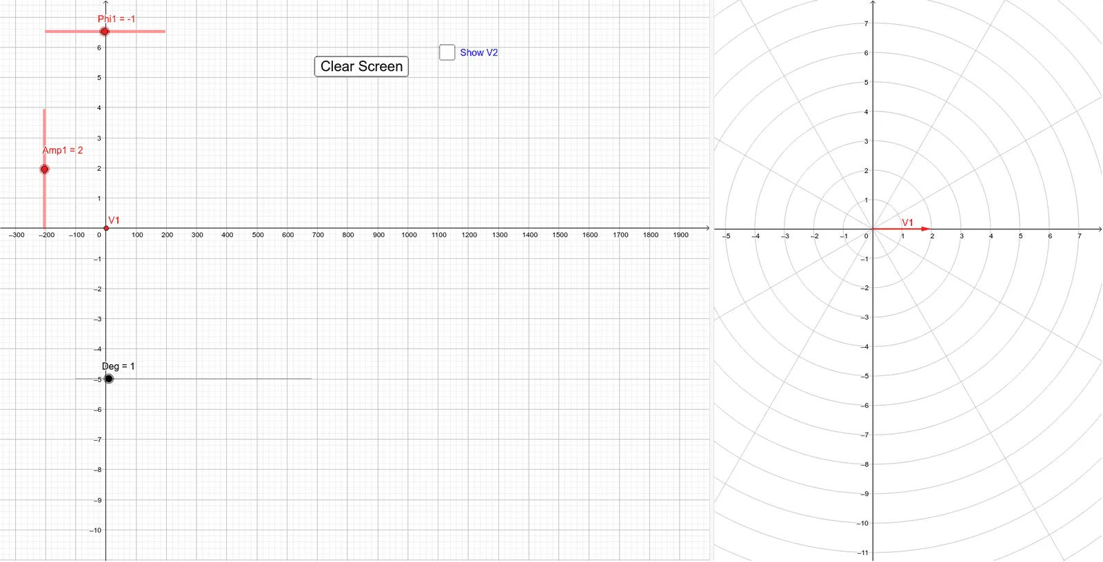
This example demonstrates the geometric addition of two phasors (vectors represented as complex numbers) and their resultant. Key math concepts include complex numbers, vector addition, trigonometry, and geometric constructions. GeoGebra commands like Point, Segment, and Vector are used to construct the phasors, with parameters such as amplitude (Amp1, Amp2), phase angle (theta, Phi1, Phi2), and components (RealV1, ImgV1). Suitable for high school physics and mathematics courses on AC circuits and signal processing.
GeoGebra Commands & Parameters
Point(xAxis) → OSegment((Deg, 0), V2) → V2tSegment((Deg, 0), V1) → V1tVector(O, PV1) → phasorV1Vector(O, PV2) → phasorV2Vector(O, PV3) → phasorV3Segment(PV1, PV3) → t1Segment(PV2, PV3) → t2
AI Drawing Prompt Reference
Draw two vectors starting from the origin representing complex numbers and show their geometric addition and resultant vector. First, draw the vectors representing the two complex numbers, then construct the parallelogram by connecting the start and end points of these vectors, and finally obtain the resultant vector.
The prompt above was compiled from the original drawing commands and is for reference only.