
Parallelepiped Construction Example
Loading the math board and drawing, please wait…
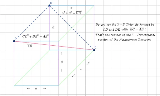
This example demonstrates the construction of a parallelepiped. Key mathematical concepts include vectors, coordinate geometry, and solid geometry. Using GeoGebra commands such as Segment and Intersect, the faces and edges of the parallelepiped are constructed. Suitable for high school mathematics education and students learning solid geometry.
GeoGebra Commands & Parameters
Segment(A, B) → fSegment(A_1, B_1) → f_1Segment(B_1, C) → gSegment(C, B) → hSegment(C_1, B_2) → h_1Segment(C_2, B_3) → h_2Segment(C_3, B_4) → h_3Segment(A_2, B_6) → f_2Segment(A_3, B_7) → f_3Segment(C_5, B_8) → h_5Segment(C_6, B_9) → h_6Segment(C_7, B_{10}) → h_4Intersect(h_3, f_2) → DIntersect(h_1, f_3) → E_1Segment(D, E_1) → iIntersect(f, f_1) → ESegment(E, E_1) → j
AI Drawing Prompt Reference
Draw a parallelepiped by first marking six vertices A, B, C, D, E, and F, then connecting them to form six edges AB, BC, CD, DA, EF, and FA. Next, draw edges parallel to AB (A1B1), BC (B1C1), and CD (C1D1), and edges parallel to DA (D1A1), EF (E1F1), and FA (F1A1). Finally, connect the corresponding vertices to form the six faces of the parallelepiped.
The prompt above was compiled from the original drawing commands and is for reference only.