
Parallel Lines Cut by a Transversal-Part 4
Loading the math board and drawing, please wait…
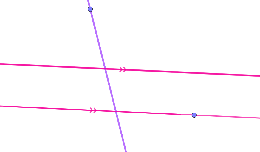
This example demonstrates the geometric relationships and angle properties formed when parallel lines are cut by a transversal. It involves core math concepts like parallel line properties, corresponding angles, alternate interior angles, similar triangles, centroid, and rectangles. The construction uses GeoGebra commands and objects such as Point, Line, Intersect, Angle, and Segment. Suitable for high school geometry teaching and learning to visually understand the properties and conclusions of parallel lines and transversals.
GeoGebra Commands & Parameters
Point(eq1) → ALine(B, A) → fLine(C, f) → gPoint(eq2) → DLine(D, E) → hIntersect(g, h) → FIntersect(f, h) → GPoint(h) → HPoint(f) → IPoint(g) → JPoint(g) → KAngle(K, F, D) → αAngle(I, G, H) → βAngle(H, G, A) → γAngle(D, F, J) → δAngle(K, F, D) → εPoint(f) → LPoint(g) → MPoint(f) → NAngle(H, G, A) → ζAngle(N, G, H) → ηAngle(D, F, M) → θPoint(g) → OPoint(f) → PAngle(D, F, O) → ιAngle(K, F, D) → κAngle(A, G, F) → λAngle(G, F, K) → μAngle(H, G, A) → νAngle(P, G, H) → ξAngle(F, G, P) → οAngle(O, F, G) → ρPoint(g) → QPoint(f) → RAngle(G, F, K) → σAngle(Q, F, G) → τAngle(A, G, F) → υAngle(F, G, R) → ϕAngle(G, F, K) → χAngle(F, G, R) → ψAngle(A, G, F) → ωAngle(Q, F, G) → α_1Point(g) → SPoint(g) → TSegment(S, T) → sPoint(f) → UPoint(f) → VSegment(U, V) → t
AI Drawing Prompt Reference
Draw two distinct parallel lines in the plane, and then draw a transversal line that intersects each parallel line. Mark the intersection points on the transversal with both parallels as the key vertices, and place several additional points on the relevant lines near those vertices so you can form multiple rays. Construct and display a set of angles using rays that come from the two intersection points, including corresponding angles and alternate interior angles. Also add a couple of segments on the lines using selected points so the diagram clearly supports comparing the angle relationships produced by the transversal cutting the parallel lines.
The prompt above was compiled from the original drawing commands and is for reference only.