
Pantograph Mechanism
Loading the math board and drawing, please wait…
In collections
Transformations
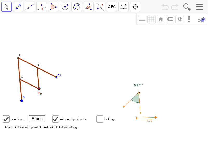
This example demonstrates the working principle of a pantograph mechanism. Core mathematical concepts include geometric construction and transformation. Using GeoGebra commands such as Circle, PointIn, Intersect, Segment, etc., the dynamic construction and observation of the pantograph mechanism's movement can be achieved. Suitable for high school or university geometry and mechanical principles courses.
GeoGebra Commands & Parameters
Circle(A, a) → fCircle(A, a + b) → ePointIn(e) → BCircle(B, b) → gIntersect(f, g, 1) → CSegment(A, C) → hSegment(C, B) → iSegment(C, D) → jSegment(D, E) → lSegment(E, F) → mSegment(B, E) → nSegment(G, H) → pCircle(I, sz) → qPoint(q) → JSegment(J, I) → rPoint(q) → KSegment(K, I) → sAngle(J, I, K) → αTextfield(a) → inputBox1Textfield(b) → inputBox2Textfield(d) → inputBox4Textfield(t) → inputBox5
AI Drawing Prompt Reference
Draw a pantograph mechanism to demonstrate its working principle, featuring two fixed points and a sliding point connected by circles and line segments to show the联动 relationship of mechanical arms. Start by drawing two concentric circles, with one intersecting at the sliding point, then use the intersection points and radii to form other segments, creating the mechanical arm structure. Add sliders to control parameters, label key angles and lengths, and clearly illustrate the movement process.
The prompt above was compiled from the original drawing commands and is for reference only.