
Isocronism: Simple Harmonic Motion from Uniform Circular Motion
Loading the math board and drawing, please wait…
In collections
El dominio del Tiempo (cinemática intuitiva)
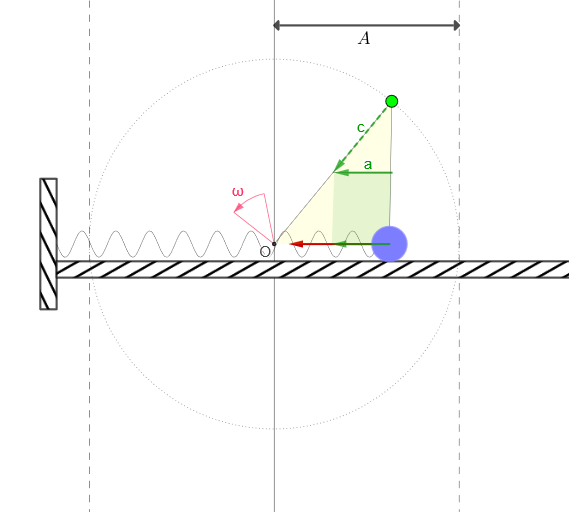
This example demonstrates isocronism by projecting uniform circular motion onto a line to obtain simple harmonic motion (SHM). It visually confirms that SHM has the same period as the generating circular motion when angular frequency is matched. Key concepts include the geometric correspondence between circular phase and SHM displacement, time-parameterized motion, and the period/frequency relationship that underlies the isocronism phenomenon. The construction uses GeoGebra elements such as Circle and Point to define the rotating reference, Angle to track the phase, Translate to shift reference positions, and CurveCartesian to draw the resulting oscillation curve from the projection. It also employs mean and Segment for establishing central references (e.g., midpoints/geometry scaffolding), plus animation/time objects to move points from t0 to t1 and compare the cycle structure. Suitable for high school through early undergraduate levels, especially for math-physics integration and interactive classroom demonstrations.
GeoGebra Commands & Parameters
Point(Segment[O, (2 * O) - P]) → QPoint(Segment[((-A), 0), (A, 0)]) → MIf(Length[reg] ≟ 1, {reg(1)}, Sequence[reg(k) - reg(k + 1), k, 1, Length[reg] - 1]) → regDifmean(regDif) → TSegment((x(Q), y(B) + 0.1), (x(O), y(B) + 0.1)) → jCircle(M, r) → cir_{1}Circle(O, A) → cirPoint(cir) → MMSegment(MM, O) → fSegment(M, MM) → gSegment(MM + c, (x(MM), y(MM + c))) → lTranslate(a, Mc) → uAngle(O + (-4, 20), O, Rotate[O + (-4, 20), ω]) → αCurveCartesian(t, (1.2 * sin(((20 * pi) * (t - (x(M) + 0.5)) / (x(P0) - (x(M) + 0.5))))), t, x(P0), x(M)) → muelle
AI Drawing Prompt Reference
Draw a graph showing simple harmonic motion (SHM) projected from uniform circular motion. The graph includes circles, points, line segments, angles, and curves. There is a geometric correspondence between the phase of circular motion and the displacement of SHM. The construction order is to first define the reference point of circular motion, then project it onto a line to obtain the SHM curve.
The prompt above was compiled from the original drawing commands and is for reference only.