
Cube Parts Demonstration by Renáta Vágová (5)
Loading the math board and drawing, please wait…
In collections
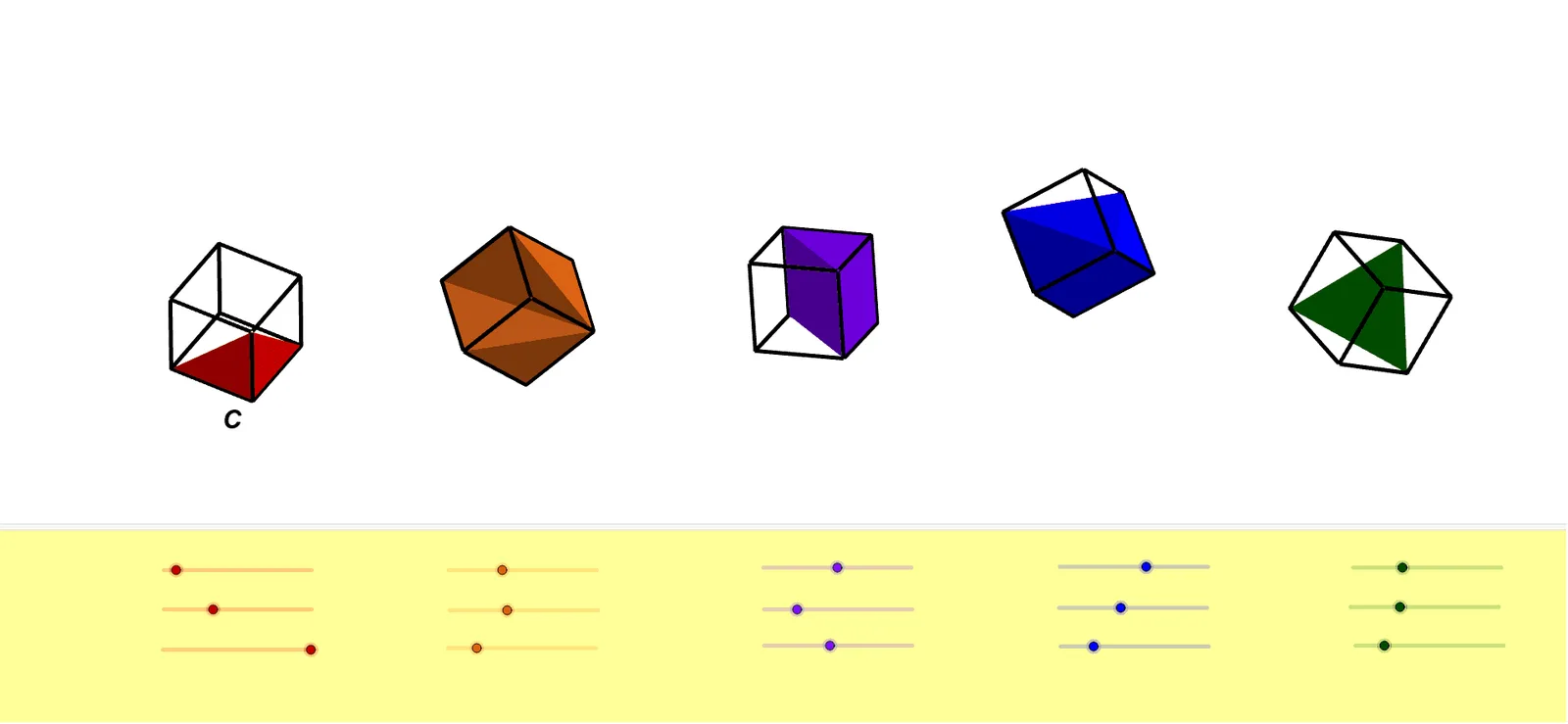
TWO PARTS OF A CUBE
This example demonstrates different parts of a cube and their geometric relationships. It involves core math concepts like solid geometry, polygons, linear programming, and logarithms. The construction uses GeoGebra commands and objects such as Point, Cube, Intersect, Line, Rotate, Polygon, and Pyramid. Suitable for high school and above students to understand spatial geometry and optimization problems.
GeoGebra Commands & Parameters
Point(xAxis) → APoint(xAxis) → BPoint(Circle[B, Distance[A, B], Segment[A, B]]) → CCube(A, B, C) → a, D, faceCDHG, faceEFGH, edgeAD, edgeAB, edgeBC, edgeCD, edgeAE, edgeDH, edgeEH, edgeEF, E, edgeBF, edgeFG, edgeCG, edgeGH, F, G, H, faceABCD, faceADHE, faceABFE, faceBCGFPoint(xAxis) → IPoint(xAxis) → JPoint(Circle[J, Distance[I, J], Segment[I, J]]) → KCube(I, J, K) → b, L, faceKLPO, faceMNOP, edgeIL_1, edgeIJ_1, edgeJK_1, edgeKL_1, edgeIM_1, edgeLP_1, edgeMP_1, edgeMN_1, M, edgeJN_1, edgeNO, edgeKO, edgeOP, N, O, P, faceIJKL, faceILPM_1, faceIJNM_1, faceJKONIntersect(yAxis, xAxis) → QPoint(xAxis) → RPoint(Circle[R, Distance[Q, R], Segment[Q, R]]) → SCube(Q, R, S) → c, T, faceSTZW, faceUVWZ, edgeQT_1, edgeQR, edgeRS_1, edgeST_1, edgeQU, edgeTZ, edgeUZ, edgeUV, U, edgeRV_1, edgeVW_1, edgeSW_1, edgeWZ, V, W, Z, faceQRST, faceQTZU, faceQRVU, faceRSWVPoint(xAxis) → A_1Point(xAxis) → B_1Point(Circle[B_1, Distance[A_1, B_1], Segment[A_1, B_1]]) → C_1Cube(A_1, B_1, C_1) → d, D_1, face5, face6, edge2, edge1, edge4, edge6, edge3, edge8, edge10, edge9, E_1, edge5, edge11, edge7, edge12, F_1, G_1, H_1, face1, face3, face2, face4Point(xAxis) → I_1Point(xAxis) → J_1Point(Circle[J_1, Distance[I_1, J_1], Segment[I_1, J_1]]) → K_1Cube(I_1, J_1, K_1) → e, L_1, face11, face12, edge14, edge13, edge16, edge18, edge15, edge20, edge22, edge21, M_1, edge17, edge23, edge19, edge24, N_1, O_1, P_1, face7, face9, face8, face10Line(A, yAxis) → fLine(I, yAxis) → gLine(A_1, yAxis) → hLine(I_1, yAxis) → iLine(A, zAxis) → jLine(I, zAxis) → kLine(A_1, zAxis) → lLine(I_1, zAxis) → mRotate(a, α, f) → a'Rotate(a', β, xAxis) → a''Rotate(a'', γ, j) → a'''Rotate(b, δ, g) → b'Rotate(b', ε, xAxis) → b''Rotate(b'', ζ, k) → b'''Rotate(c, (-η), yAxis) → c'Rotate(c', θ, xAxis) → c''Rotate(c'', ι, zAxis) → c'''Rotate(d, κ, h) → d'Rotate(d', λ, xAxis) → d''Rotate(d'', μ, l) → d'''Rotate(e, ν, i) → e'Rotate(e', ξ, xAxis) → e''Rotate(e'', ο, m) → e'''Polygon(B, G, E) → t1, e_1, b_1, g_1Polygon(E, B, F) → t2, f_1, e_2, b_2Polygon(E, F, G) → t3, g_2, e_3, f_2Polygon(B, G, F) → t4, f_3, b_3, g_3Rotate(t1, α, f) → t1'Rotate(t1', β, xAxis) → t1''Rotate(t1'', γ, j) → t1'''Rotate(t3, α, f) → t3'Rotate(t3', β, xAxis) → t3''Rotate(t3'', γ, j) → t3'''Rotate(t4, α, f) → t4'Rotate(t4', β, xAxis) → t4''Rotate(t4'', γ, j) → t4'''Rotate(t2, α, f) → t2'Rotate(t2', β, xAxis) → t2''Rotate(t2'', γ, j) → t2'''Pyramid(L, I, M, P, K) → n, faceILPM, edgeKL, edgeIK_1, edgeKM_1, edgeKP, faceIKL, faceIKM_1, faceKMP, faceKLP, edgeIL, edgeIM_2, edgeMP, edgeLPPyramid(M, I, J, N, K) → o, faceIJNM, edgeKM, edgeIK, edgeJK, edgeKN, faceIKM, faceIJK, faceJKN, faceKMN, edgeIM, edgeIJ, edgeJN, edgeMNRotate(n, δ, g) → n'Rotate(n', ε, xAxis) → n''Rotate(n'', ζ, k) → n'''Rotate(o, δ, g) → o'Rotate(o', ε, xAxis) → o''Rotate(o'', ζ, k) → o'''Point(c''') → Q_1Pyramid(Q, Q_1, R, S, T, W) → p, face15, edgeST, edgeQT, edgeQW, edge27, edgeRW_1, edgeSW, edgeTW, face13, face14, faceRSW, faceSTW, faceQTW, edge25, edge26, edgeRSPyramid(Q_1, R, W, V) → q, face17, edgeVW, face16, faceRVW, face18, edge28, edgeRW, edge30, edge29, edgeRVRotate(p, (-η), yAxis) → p'Rotate(p', θ, xAxis) → p''Rotate(p'', ι, zAxis) → p'''Rotate(q, (-η), yAxis) → q'Rotate(q', θ, xAxis) → q''Rotate(q'', ι, zAxis) → q'''Pyramid(A_1, B_1, C_1, D_1, F_1) → r, face23, edge33, edge35, edge37, edge38, face19, face21, face22, face20, edge31, edge34, edge36, edge32Pyramid(D_1, A_1, E_1, H_1, F_1) → s, face28, edge42, edge41, edge44, edge46, face24, face25, face27, face26, edge39, edge40, edge45, edge43Pyramid(C_1, D_1, H_1, F_1) → t, face30, edge52, face29, face32, face31, edge47, edge51, edge49, edge48, edge50Rotate(r, κ, h) → r'Rotate(r', λ, xAxis) → r''Rotate(r'', μ, l) → r'''Rotate(s, κ, h) → s'Rotate(s', λ, xAxis) → s''Rotate(s'', μ, l) → s'''Rotate(t, κ, h) → t'Rotate(t', λ, xAxis) → t''Rotate(t'', μ, l) → t'''Pyramid(L_1, I_1, J_1, M_1) → u, face33, edge57, face35, face34, face36, edge54, edge53, edge56, edge58, edge55Rotate(u, ν, i) → u'Rotate(u', ξ, xAxis) → u''Rotate(u'', ο, m) → u'''
AI Drawing Prompt Reference
Draw a cube to demonstrate its different parts and geometric relationships. First, create three cubes, each defined by three points on the x-axis spaced equally. Then, draw three lines along the y-axis and z-axis, and rotate each cube around these lines to show different perspectives. Finally, connect the vertices of the cubes to form multiple polygonal faces, highlighting the structure and spatial relationships of the cube.
The prompt above was compiled from the original drawing commands and is for reference only.